


在以往的锂离子电池负极材料中,SiO2的理论比容量高、体积膨胀小、储量丰富。但是,无机SiO2材料的导电性低,将其加工到纳米级才能发生Faraday反应,制备工艺复杂且成本较高。天然硅藻生物SiO2 (Diatom based silica, DBS)具有纳米尺度中空多孔结构,可缓解循环过程的体积膨胀[6]。硅藻是一种单细胞真核藻类,能吸收环境中的硅酸并通过生物硅化将其转化为SiO2壳体。用硅藻壳体制备锂离子电池的负极,具有优异的电化学性能。硅藻壳体复杂的中空层状多孔结构可抑制其体积膨胀(< 150%),但是较低的电导率使其初始库仑效率降低。因此,必须提高硅藻壳体负极材料的电导率。为了解决这一问题,可将硅藻壳体与高导电性的碳或金属元素复合。Wang等[7]将三种硅藻除杂和煅烧,制备出倍率性能和可逆容量优良的锂离子电池负极材料。同时,硅藻壳体复杂的层状多孔结构可抑制锂化/去锂化对微观结构的破坏,硅藻的原生碳组分也能提高SiO2的导电性。Chen等[8,9]采用金属螯合和用巯基硅烷代替无机硅源引入S活性位点负载Ag+,制备出金属Co纳米颗粒和Ag纳米颗粒负载的硅藻壳体SiO2负极材料,具有优异的电化学性能。但是,Co和Ag的价格昂贵。稀土元素(Rare earth elements, REE),包括由La到Lu等的VI族元素,具有独特的物理化学性质[10]。稀土元素的储量丰富,已经广泛应用于催化、燃料电池、光学和军事等领域[11]。大多数稀土元素具有氧化还原偶对,表明用于储能在热力学上是可行的[12~14]。已有的研究大多集中在锂离子电池正极材料或电解质中掺杂和修饰稀土元素[15~17]。如Luo等[18]用固相合成法将La掺杂到LiFePO4正极材料中,将晶格尺寸减小到纳米级,使其电导率、锂离子扩散速率和电极的可逆比容量提高。Zhang等[19]用抗坏血酸水热法将La和Y共掺杂到LiFePO4中,在电流密度为0.2 C循环时其比放电容量为160.56 mAh·g-1。DFT计算结果表明,掺杂La和Y可提高材料的载流密度,制备的电极材料电化学性能优异。同时,稀土金属氧化物具有良好的氧化还原特性、丰富的氧空位和较高的热稳定性,在储能领域也得到了应用。目前,已经有用稀土元素制备电池负极材料的研究[20]。Wang等[21]用三步合成法制备了CeO2@Carbon/SNBT电极材料,发现稀土元素的掺杂使CeO2@Carbon/SNBT负极材料的电化学性能显著优于未掺杂稀土元素的负极材料(SNBT)。Zheng等[22]将稀土元素三氢化合物(REH3, RE = La, Y, Gd)与石墨混合球磨制备复合材料,循环250次后的放电比容量约为720 mAh·g-1。其原因是,REH3中的活性氢引入带负电荷的位点增强了Li+与石墨烯层的结合,从而生成有利于能量储存的锂化产物Li5C16H。Yin等[23]进行稀土掺杂显著提高了氧化铌电极的倍率性能。稀土元素在钠离子电池、锂硫电池,水系锌离子电池、锂金属负极等方面也有重要的应用[24~27]。鉴于此,本文基于硅藻的生物矿化行为制备稀土离子掺杂的硅藻生物SiO2负极材料,研究稀土元素对硅藻的生长、壳体结构和电化学性能的影响,以及稀土离子修饰对硅藻壳体微观结构及其电化学性能的影响。
1 实验方法
1.1 制备稀土提取液
将100 g离子型稀土矿置于锥形瓶中并加入蒸馏水1 L,将瓶口封住后置于121 ℃高压灭菌锅中灭菌30 min,冷却后加入(NH4)2SO4使其浓度为2%,振荡30 min浸提稀土离子,离心后收集上清液(即稀土提取液)并将其保存在4 ℃冰箱中。
用ICP-OES (Agilent 5110)测定稀土提取液中各种稀土元素的浓度(mg·L-1)为: La 0.179,Ce 0.231,Pr 0.231,Nd 0.234,Sm 0.229,Eu 0.242,Gd 0.167,Tb 0.247,Dy 0.222,Ho 0.210,Er 0.171,Tm 0.186,Yb 0.062,Lu 0.122,Sc 0.084,Y 0.116。含有16种稀土元素的稀土提取液,其浓度为0.062~0.247 mg/L。稀土提取液中还有浓度为4.428 mg/L的Si。
1.2 培养硅藻
在3 L锥形瓶中用2 L体系培养实验用硅藻(舟形藻,Navicula sp.),培养基为人工海水+F/2培养基,接种密度为120 个/mL,光照为2500 lx,温度为25 ℃,在12 h光照/12 h黑暗条件下培养10 d。
在2 L培养基中分别加入0、5、10、20 mL稀土提取液,得到稀土提取液添加量分别为0、2.5、5、10 mL/L的培养体系。每隔2 d取样一次,检测培养基的pH值、叶绿素a、类胡罗卜素含量和Si浓度。培养结束后收集藻液并进行离心分离,得到稀土共培养硅藻。为了去除稀土共培养硅藻中的杂质,将其浸泡在体积分数为5%的稀盐酸中6 h,然后用无水乙醇充分洗涤(1~2次),离心分离后将其冷冻干燥。
将收集到的稀土共培养硅藻干粉在Ar气氛中以5 ℃/min的速率加热至600 ℃碳化3 h,得到稀土离子掺杂的硅藻负极材料。不同的硅藻负极材料,分别记为DBS@C-REE-2.5、DBS@C-REE-5和DBS@C-REE-10。将未添加稀土培养的硅藻负极材料记为DBS@C。
1.3 测定光合色素浓度
将2 mL硅藻培养物离心5 min (转速为10000 r/min),分离出硅藻沉淀。将硅藻沉淀溶解在体积分数为90%甲醇水溶液中得到硅藻甲醇溶液,在温度为4 ℃的黑暗条件下保存24 h。使用紫外-可见分光光度计(ND-100)在470、652.4和665.2 nm波长处读取硅藻甲醇溶液的吸光度,用以下公式计算光合色素叶绿素a、叶绿素b和类胡萝卜素浓度(mg·L-1)。
其中Ca、Cb和Cc分别为叶绿素a、叶绿素b和类胡萝卜素的浓度(mg·L-1),A665.2、A652.4和A470分别为硅藻沉淀在665.2、652.4和470 nm波长处的吸光度。
1.4 测定硅浓度
配制体积分数为50%的盐酸、浓度为100 g/L的钼酸铵和62.5 g/L的草酸溶液以及还原剂(2 g NaHSO3 + 0.1 g氨基-萘酚-磺酸 + 0.2 g Na2SO3 + 10 mL H2O),在2 mL硅藻甲醇溶液中加入40 μL的HCl和80 μL钼酸铵,摇匀后静置5 min,然后加入80 μL草酸溶液,摇匀后静置5 min。再加入80 μL的还原剂,摇匀后静置5 min,使用紫外分光光度计测定溶液在650 nm处的吸光度,根据标准曲线计算硅浓度。
1.5 表征材料的性能
采用X射线粉末衍射仪(XRD, Rigaku Smart Lab SE)测定未经修饰的和稀土离子掺杂的硅藻负极材料的XRD谱。用热重分析仪(TGA, PerkinElmer TL8000)分析稀土离子掺杂的硅藻负极材料的热解行为。用扫描电镜(SEM, MIRA3 LMH)和透射电镜(TEM, TF20)观察硅藻壳体的微观结构。用能量散射X射线光谱仪(EDS, Ultim Max 40)分析稀土离子掺杂的硅藻负极材料的元素组成以及分布。用拉曼光谱仪(LabRAM HR)表征样品的碳材料特性。
1.6 组装半电池和测试电化学性能
将制备的稀土离子掺杂硅藻负极材料与炭黑(Super P)、聚偏二氟乙烯(PVDF)按7∶2∶1的质量比混合,加入适量的N-甲基吡咯烷酮(NMP),以500 r/min的转速球磨3 h,得到混合均匀的电极浆料。在铜箔上涂布厚度为50 μm的浆料,然后将其在80 ℃真空干燥。将干燥后涂有浆料的铜箔裁成直径为12 mm的圆形电极片并在其表面滴加30 μL的电解液。在充满氩气的手套箱中将裁切好的圆片电极放到盒的下部,再放上隔膜并滴加30 μL的电解液,最后放入锂片后盖上盖并用封装机封口组装成扣式电池即半电池。
测试半电池循环伏安(Cyclic voltammetry, CV)曲线:用双电极体系,以0.5 mV/s的速度对半电池进行循环扫描,分析电极材料在充放电过程中的电化学反应过程、容量变化和极化程度等;测试电化学阻抗谱(Electrochemical impedance spectroscopy, EIS):对半电池施加频率为105~10-2 Hz的信号电压,分析电极材料的阻抗;测试恒电流充放电性能:对半电池施加100 mA·g-1的恒定电流,研究电极材料的充放电效率、比容量和循环性能;测试循环性能:对半电池施加不同电流密度(0.1、0.2、0.5、1.0和2.0 A·g-1)的电流,研究电极材料的循环性能。以上电化学测试采用Gamry电化学工作站以及蓝电电池测试系统进行,工作电位区间为0.01~3 V。赝电容(Pseudocapacitance)分析:使用Gamry电化学工作站分别在0.2、0.5、0.8、1.0、1.5、2.0 mV/s速率下对半电池进行循环扫描,使用Origin软件对不同扫速的循环伏安数据进行拟合、分析并计算赝电容贡献率,根据测试结果和拟合数据分析半电池在不同扫速下的循环伏安特性和赝电容贡献率。
2 结果和讨论
2.1 稀土提取液添加量对硅藻生长的影响
图1给出了稀土提取液添加量不同的硅藻生长和溶液理化参数。由图1a可见,在培养周期内溶液体系的pH值呈上升的趋势,是培养基中的硅酸盐被硅藻吸收所致。添加稀土提取液的实验组其pH值均低于未添加稀土提取液的对照组。其原因,一是稀土提取液的浸提液是硫酸铵,稀土提取液的初始pH值为酸性;二是稀土离子对硅藻生长的抑制减缓硅藻对环境中硅酸的吸收。检测硅藻叶绿素a与类胡罗卜素含量的变化(图1b和c)发现,添加稀土提取液体系中硅藻的叶绿素和类胡罗卜素的含量均低于未添加稀土提取液的硅藻。其原因,可能是稀土提取液中的某种元素或几种元素对硅藻的毒性积累所致。高浓度的稀土元素对水生生物有不利的影响,例如Ce元素损伤藻类的细胞膜进而抑制其生长[28]。图1d中培养基体系Si含量的变化曲线表明,未添加稀土提取液的体系中Si的消耗最快,在第4 d即达到Si“饥饿”状态。稀土元素使硅藻对Si的摄入减缓从而抑制硅藻的生长。抑制程度随着稀土离子浓度的提高而加强。
图1
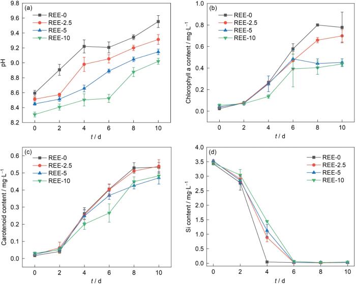
图1
稀土提取液添加量不同的硅藻生长和溶液理化参数
Fig.1
Physiological and biochemical parameters of diatom growth process under the conditions of different concentration of REE extraction solution (a) pH curve, (b) chlorophyll a concentration, (c) carotenoid concentrations, (d) Si concentration
2.2 材料的组成和结构
图2a中的XRD谱中以22°为中心的宽峰对应的物相为SiO2。宽衍射峰表明,SiO2是非晶态。与晶态SiO2相比,非晶态SiO2的Si-O键结合能较低,更容易断裂而提高其电化学活性。同时,DBS@C的谱中位于24.8°的衍射峰对应材料中的C。C在稀土离子掺杂的硅藻负极材料中消失,可能是稀土元素催化了C的裂解。DBS@C-REE-2.5和DBS@C-REE-5中宽峰的位移可能是样品的测试高度不同引起的。根据TG曲线测定了样品中各组分的含量(图2b)。无定形SiO2·nH2O的玻璃转变点约为1200 ℃[29],因此在40~740 ℃不会发生[SiO4]四面体的长程有序化和结晶化。图2b表明,样品的质量损失分为两个阶段。第一阶段发生在40~300 ℃,其质量损失归因于无定形SiO2·nH2O的脱水;第二阶段发生在400~700 ℃,其质量损失归因于C的损失(C+O2→CO2);其余部分为SiO2。表1给出了不同稀土提取液添加量制备的稀土离子掺杂的硅藻负极材料中各成分含量。由表1可见,随着稀土含量的提高C的含量降低,与XRD谱给出的结果一致。值得注意的是,在100~300 ℃区间DBS@C-REE-10质量的增加可能是样品中稀土元素氧化所致。
图2
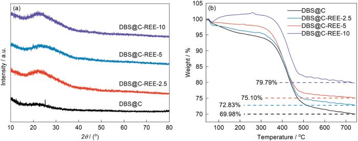
图2
稀土含量不同的稀土离子掺杂的硅藻负极材料的XRD谱和TG曲线
Fig.2
Characterization of composites with different rare earth content (a) XRD patterns, (b) TG curves
表1 不同稀土含量的稀土离子掺杂的硅藻负极材料的成分
Table 1
| Sample | H2O | C | SiO2 |
|---|---|---|---|
| DBS@C | 6.97 | 23.05 | 69.98 |
| DBS@C-REE-2.5 | 5.86 | 21.91 | 72..83 |
| DBS@C-REE-5 | 3.89 | 21.01 | 75.10 |
| DBS@C-REE-10 | 0.93 | 19.28 | 79.79 |
图3给出了稀土离子掺杂的硅藻负极材料的微观结构。可以看出,未经修饰的硅藻壳体表面光滑,没有纳米颗粒或团簇负载,其尺寸为5~10 μm,表面有均匀的孔径和分层结构。从图3中的虚线区域可见硅藻壳体的中空结构和厚度约为50 nm的碳层。碳层来源于硅藻生物体内的有机生物质,碳层的包覆可提高SiO2的导电性。在稀土离子掺杂的硅藻负极材料中,稀土提取液中各元素的浓度较低,不能达到晶体成核的过饱和条件,因此不能在硅藻壳体的表面聚集形成可视的晶体结构。从图4可见,硅藻壳体表面分布有少量的稀土元素。这表明,稀土离子成功的掺入到硅藻生物SiO2结构中。其原因是,硅藻的生长进入Si“饥饿”状态后,硅藻须从周围环境中吸收金属微量元素并通过生物矿化作用掺入自身的SiO2壳体结构内。
图3
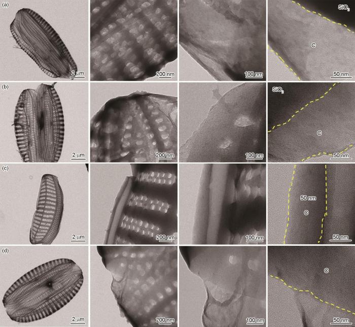
图3
稀土含量不同的稀土离子掺杂的硅藻负极材料的透射电镜和高分辨透射电镜图像
Fig.3
TEM and HRTEM images of composites with different rare earth contents (a) DBS@C, (b) DBS@C-REE-2.5, (c) DBS@C-REE-5, (d) DBS@C-REE-10
图4
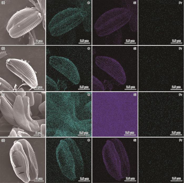
图4
稀土含量不同的稀土离子掺杂的硅藻负极材料的扫描电镜照片和EDS映射谱
Fig.4
SEM images and EDS mapping of composites with different rare earth contents (a) DBS@C, (b) DBS@C-REE-2.5, (c) DBS@C-REE-5, (d) DBS@C-REE-10
图5
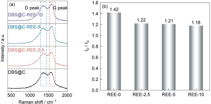
图5
稀土含量不同的稀土离子掺杂的硅藻负极材料的Raman光谱
Fig.5
Raman of composites with different rare earth contents (a) Raman spectra, (b) ID/IG integration intensity ratio
2.3 电化学性能
图6a~d给出了DBS@C以及DBS@C-REE电极材料的CV测试结果。可以看出,在第一次阴极扫描中,1.2 V附近的还原峰对应体系中固体电解质界面层的形成,0.2 V附近的还原峰归因于SiO2的锂化反应(反应式(4)~(6)),位于0.01 V的峰对应Si的合金化反应(
图6

图6
稀土提取液添加量不同的硅藻壳体负极的电化学性能
Fig.6
Electrochemical performance of diatom frustule-based anode with different concentration of REE extraction solution, CV curves of DBS@C (a), DBS@C-REE-2.5 (b), DBS@C-REE-5 (c), DBS@C-REE-10 (d), long cycle performance of DBS@C-REE (e), rate performance of DBS@C-REE (f)
表2 稀土提取液添加量不同的硅藻壳体负极的倍率
Table 2
| Sample | 0.1 A·g-1 | 0.2 A·g-1 | 0.5 A·g-1 | 1 A·g-1 | 2 A·g-1 |
|---|---|---|---|---|---|
| DBS@C | 211.9 | 143.3 | 88.3 | 58.1 | 33.7 |
| DBS@C-REE-2.5 | 266.6 | 242.5 | 204.5 | 114.5 | 145.7 |
| DBS@C-REE-5 | 321.1 | 290.2 | 245.6 | 139.8 | 174.6 |
| DBS@C-REE-10 | 348.1 | 316.9 | 269.7 | 162.1 | 199.6 |
根据电化学阻抗的测试结果分析了DBS@C-REE电极的界面和阻抗。如图7a所示,在105~10-2 Hz频率范围内进行了EIS测试并建立了等效电路模型。可以看出,EIS曲线由一个半圆和一条斜线组成。在实轴上的截距为溶液阻抗(Rs),电极的电荷转移电阻(Rct)由中频区域的半圆决定,低频区的斜线归因于Warburg阻抗,与电极材料中Li+的扩散有关。图7a、b表明,随着稀土离子含量的提高DBS@C-REE负极的电荷转移阻抗随之降低。DBS@C负极的高阻抗表明,组成硅藻壳体的SiO2的导电性低,而DBS@C-REE负极中稀土元素则提高了SiO2的外在导电性,使DBS@C-REE负极的阻抗显著降低,有利于提高SiO2负极的倍率性能。根据EIS曲线计算出Li+的扩散系数为
图7
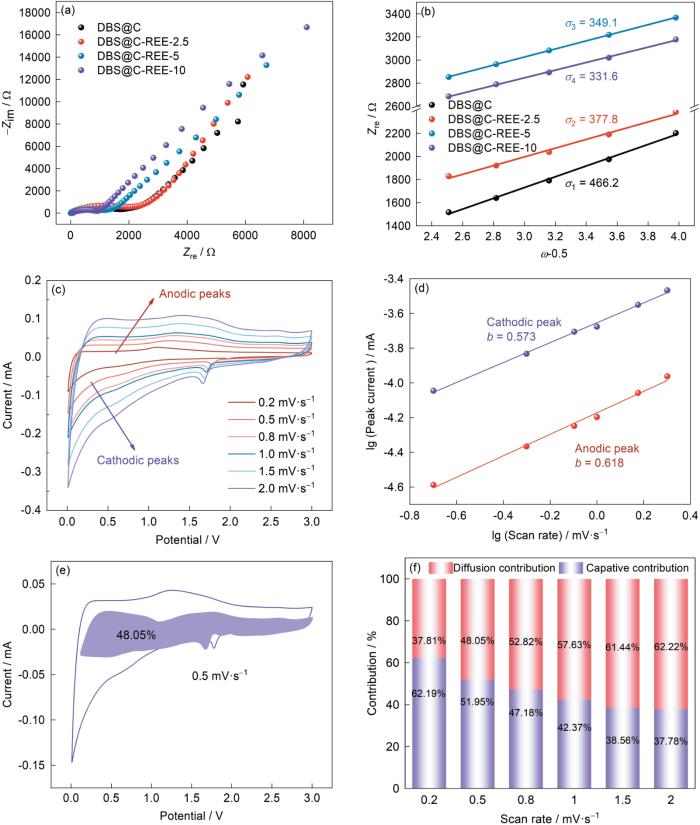
图7
稀土含量不同稀土离子掺杂的硅藻负极材料的交流阻抗和赝电容
Fig.7
EIS and pseudocapacitance test results of composites with different rare earth content (a) Nyquist curve, (b) Warburg factor, (c~f) pseudocapacitance contribution of DBS@C-REE-10
表3 DBS@C-REE电极材料的Warburg因子和Li+扩散系数
Table 3
| Sample | DLi+ / cm2·s-1 | |
|---|---|---|
| DBS@C | 466.2 | 2.17 |
| DBS@C-REE-2.5 | 377.8 | 3.30 |
| DBS@C-REE-5 | 349.1 | 3.86 |
| DBS@C-REE-10 | 331.6 | 4.28 |
DBS负极导电性的提高有利于Li+在体相中的扩散。稀土元素的负载不仅提高了DBS的导电性,还显著提高了电极材料的容量和倍率性能。
为了阐明DBS@C-REE电极材料的电化学反应机制,测试了DBS@C-REE-10的赝电容(图7c~f)。DBS@C-REE-10的电化学行为可表示为
其中i、
由
可确定电容和扩散控制的容量,其中
3 结论
(1) 浓度过高的稀土提取液抑制硅藻的生长。稀土离子通过硅藻的生物矿化掺入硅藻壳体的SiO2结构,高温碳化后硅藻体内的有机生物质转化为硅藻壳体表面厚度约50 nm的导电碳层,使SiO2的导电性提高。
(2) 随着稀土元素含量的提高电极的长循环性能和倍率性能显著提高。稀土离子的修饰不仅使SiO2的导电性提高,还能降低SiO2的电化学阻抗而提高Li+的扩散速率。
参考文献
Electrical energy storage for transportation-approaching the limits of, and going beyond, lithium-ion batteries
[J].
Where do batteries end and supercapacitors begin?
[J].
Materials for electrochemical capacitors
[J].
Electrochemical capacitors, also called supercapacitors, store energy using either ion adsorption (electrochemical double layer capacitors) or fast surface redox reactions (pseudo-capacitors). They can complement or replace batteries in electrical energy storage and harvesting applications, when high power delivery or uptake is needed. A notable improvement in performance has been achieved through recent advances in understanding charge storage mechanisms and the development of advanced nanostructured materials. The discovery that ion desolvation occurs in pores smaller than the solvated ions has led to higher capacitance for electrochemical double layer capacitors using carbon electrodes with subnanometre pores, and opened the door to designing high-energy density devices using a variety of electrolytes. Combination of pseudo-capacitive nanomaterials, including oxides, nitrides and polymers, with the latest generation of nanostructured lithium electrodes has brought the energy density of electrochemical capacitors closer to that of batteries. The use of carbon nanotubes has further advanced micro-electrochemical capacitors, enabling flexible and adaptable devices to be made. Mathematical modelling and simulation will be the key to success in designing tomorrow's high-energy and high-power devices.
Challenges and recent progress in the development of Si anodes for lithium-ion battery
[J].
Challenges for rechargeable Li batteries
[J].
Silica from diatom frustules as anode material for Li-ion batteries
[J].In spite of its insulating nature, SiO2 may be utilized as active anode material for Li-ion batteries. Synthetic SiO2 will typically require sophisticated synthesis and/or activation procedures in order to obtain a satisfactory performance. Here, we report on diatom frustules as active anode material without the need for extensive activation procedures. These are composed primarily of silica, exhibiting sophisticated porous structures. Various means of optimizing the performance were investigated. These included carbon coating, the addition of fluoroethylene carbonate (FEC) and vinylene carbonate (VC) to the carbonate-based electrolyte, as well as activation by an initial potentiostatic hold step. The highest capacity (723 mA h g(-1)) was obtained with composite electrodes with pristine diatom frustules and conventional carbon black as additive, with the capacity still increasing after 50 cycles. The capacity was around 624 mA h g(-1) after subtraction of the contributions from the carbon black. Carbon coated diatom frustules showed a slightly lower but stable capacity after 50 cycles (600 mA h g(-1) after subtraction of contributions from the carbon coating and the carbon black). By the use of electrochemical characterization methods, as well as post-mortem studies, differences in reaction mechanisms could be identified and attributed to the operating and processing parameters.
Cultured diatoms suitable for the advanced anode of lithium ion batteries
[J].
Diatom frustules decorated with Co nanoparticles for the advanced anode of Li-ion batteries
[J].
Developing a novel lithium-ion battery anode material via thiol functionalization of diatom frustules plus Ag modification
[J].
Issues and challenges facing rechargeable lithium batteries
[J].
Silicon oxides: a promising family of anode materials for lithium-ion batteries
[J].Silicon oxides have been recognized as a promising family of anode materials for high-energy lithium-ion batteries (LIBs) owing to their abundant reserve, low cost, environmental friendliness, easy synthesis, and high theoretical capacity. However, the extended application of silicon oxides is severely hampered by the intrinsically low conductivity, large volume change, and low initial coulombic efficiency. Significant efforts have been dedicated to tackling these challenges towards practical applications. This Review focuses on the recent advances in the synthesis and lithium storage properties of silicon oxide-based anode materials. To present the progress in a systematic manner, this review is categorized as follows: (i) SiO-based anode materials, (ii) SiO2-based anode materials, (iii) non-stoichiometric SiOx-based anode materials, and (iv) Si-O-C-based anode materials. Finally, future outlook and our personal perspectives on silicon oxide-based anode materials are presented.
Rare earth incorporated electrode materials for advanced energy storage
[J].
Rare earth elements as critical raw materials: Focus on international markets and future strategies
[J].
Efficient visible-light photocatalytic water splitting by minute amounts of gold supported on nano-particulate CeO2 obtained by a biopolymer templating method
[J].
Rare earth and transitional metal colloidal supercapacitors
[J].
Review: on rare-earth perovskite-type negative electrodes in nickel-hydride (Ni/H) secondary batteries
[J].
Lanthanum-doped LiCoO2 cathode with high rate capability
[J].
Influence of lanthanum doping on performance of LiFePO4 cathode materials for lithium-ion batteries
[J].
Effect of lanthanum and yttrium doped LiFePO4 cathodes on electrochemical performance of lithium-ion battery
[J].
Structural, electronic, and Li migration properties of RE-doped (RE = Ce, La) LiCoO2 for Li-ion batteries: a first-principles investigation
[J].
Organic-rare earth hybrid anode with superior cyclability for lithium ion battery
[J].
Synergism of rare earth trihydrides and graphite in lithium storage: Evidence of hydrogen-enhanced lithiation
[J].
Enhancing the rate capability of niobium oxide electrode through rare-earth doping engineering
[J].
Lanthanide doping induced electrochemical enhancement of Na2Ti3O7 anodes for sodium-ion batteries
[J].
A sandwich-type sulfur cathode based on multifunctional ceria hollow spheres for high-performance lithium-sulfur batteries
[J].
Superior-performance aqueous zinc ion battery based on structural transformation of MnO2 by rare earth doping
[J].
Electrolytes for batteries with earth-abundant metal anodes
[J].
Physicochemical characterization and ecotoxicological assessment of CeO2 nanoparticles using two aquatic microorganisms
[J].
Formation and thermal stability of dual glass phases in the h-BN/SiO2/Yb-Si-Al-O composites
[J].
Lithium electrochemistry of SiO2 thin film electrode for lithium-ion batteries
[J].
Quartz (SiO2): A new energy storage anode material for Li-ion batteries
[J].
