


重轨钢在大载荷和交变应力条件下服役,疲劳失效是其常见的失效形式之一[1~5]。因此,疲劳失效一直是开发和设计重轨钢产品考虑的重点。相关研究人员基于线弹性或弹塑性力学理论,从疲劳裂纹受力的角度采用模拟方法研究了重轨钢的疲劳裂纹扩展[6~10]。Nejad等[11]用有限元法研究了周期性过载对铁路用900A级珠光体钢轨疲劳裂纹扩展的应力场,发现珠光体钢轨的疲劳裂纹扩展对周期性过载高度敏感。Fang等[12]建立了包含钢轨初始裂纹的轮轨三维有限元模型,评估了初始裂纹角度、深度和尺寸对实际载荷下混合疲劳裂纹扩展行为的影响,认为45°是初始裂纹的最危险角度,导致初始裂纹深度增大和裂纹扩展速率提高。马晓川等[13]基于近场动力学理论建立了钢轨疲劳裂纹萌生的数值模拟预测模型,与经典连续介质力学模型有很好的一致性。Hasan等[14]研究了115RE和136RE钢轨在实际工况中服役的可靠性与弯曲疲劳应力之间的关系,提出了承受最大弯曲疲劳应力和疲劳试验载荷的建议值。Akama等[15]针对RP钢轨建立了非比例混合模式载荷下长共面I/II/III疲劳裂纹扩展模型,提出考虑裂纹表面接触的等效应力强度因子范围并成功回归了二次裂纹的增长率数据。Gao等[16]根据疲劳裂纹扩展的应力强度因子分析了疲劳裂纹生成的原因,认为珠光体钢轨裂纹扩展是裂纹尖端反复锐化和钝化的过程,其本质是裂纹尖端的塑性变形累积。Bonniot等[17]进一步研究了R260珠光体钢轨II+III混合模式下的疲劳裂纹扩展门槛值,构建了适用于裂纹尖端剪切/拉伸驱动的疲劳损伤模型,用于疲劳裂纹扩展路径和扩展速率的预测。
但是,以上研究大多借助有限元法评定钢轨材料的疲劳裂纹和研究应力对钢轨疲劳裂纹扩展速率及路径的影响,或者采用近场动力学方法预测钢轨的疲劳裂纹萌生位置,虽然能较直观地观察裂纹尖端应力应变场但是缺少实验佐证。因此,只用模拟方法分析疲劳结构有一定的局限性。
1 实验方法
实验用珠光体重轨钢的化学成分列于表1。三种重轨钢的在线热处理工艺为:1#试样:轧后从900℃空冷到室温(简称在线轧态);2#试样:轧后从900℃空冷到750℃,然后风冷到室温(简称在线热处理态)。3#试样(实验室热处理态):对1#试样进一步进行实验室热处理。在电阻加热炉中将1#试样加热至900℃,保温15 min后取出用水雾喷冷到560℃,保温30 s后继续水雾喷冷至室温。
表1 珠光体重轨钢的化学成分
Table 1
| C | Si | Mn | V | Cr | RE (Ce and La ratio) |
|---|---|---|---|---|---|
| 0.76 | 0.61 | 0.89 | 0.07 | 0.28 | 0.002 |
根据《43kg/m-75kg/m钢轨订货技术条件》(TB/T2344--2012)确定标准紧凑拉伸疲劳试样(CT)。在Sincotec高频疲劳试验机上进行疲劳裂纹扩展试验,设定最大、最小载荷分别为Fmax = 8 kN、Fmin = 4 kN,应力比R = 0.5。按照《金属材料疲劳试验疲劳裂纹扩展方法》(GB T 6398-2017)用显微目测法观测疲劳裂纹长度,并记录循环次数。在试样表面喷漆制作散斑,用SincoTec电磁共振高频疲劳实验机进行拉-拉疲劳实验,用XTDIC三维全场应变系统纪录和观测试样在裂纹长度为1、2、3 mm和加载力为8 kN时的裂纹尖端应变云图,以分析疲劳失效过程和机理。疲劳试验设备如图1所示。
图1

图1
CT疲劳试验设备
Fig.1
CT fatigue test (a) sampling location and actual specimen; (b) specimen size (mm); (c) fatigue loading process and strain measurement; (d) strain acquisition
将试样抛光并用4%的硝酸酒精腐蚀,用蔡司光学显微镜观察组织形貌,用GALA3 TESCAN场发射扫描电镜观察其珠光体片层,用Image J分析测量软件测量和统计晶粒尺寸和珠光体片层间距。
2 应力场和应变场的数值模拟
表2 三种试样的弹性模量和泊松比
Table 2
| Samples | 1# | 2# | 3# |
|---|---|---|---|
| Elastic modulus/MPa | 196000 | 210000 | 230000 |
| Poisson's ratio (ν) | 0.27 | 0.3 | 0.3 |
图2
在Abaqus中建立3D模型可变型实体拉伸,图3给出了CT网格模型和受力图,模型的单元类型选为C3D8R(八节点六面体线形减缩积分),共有27130个C3D8R单元和30831个节点。在Abaqus中定义相关载荷和边界条件,上下加载孔中心分别与上下加载柱面定义耦合(Cou-pling)约束关系,下加载孔中心约束X-Y-Z方向的平移和转动。根据材料的单调屈服和极限应力评估应力-应变曲线:
式中:RP0.2为屈服强度,N为应变硬化系数,可由以下表达式确定:
图3
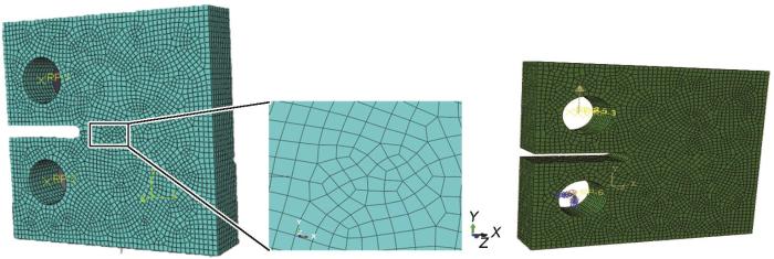
图3
CT网格模型和网格受力
Fig.3
Grid model diagram and grid stress diagram of CT specimen
表3 Franc3D模型参数
Table 3
| Fatigue load spectrum | Load / kN | Stress ratio, R | Frequency / Hz | Load form |
|---|---|---|---|---|
| Load Ⅰ | 8 | 0.5 | 45 | Sine wave |
| Load Ⅱ | 4 | 0.5 | 45 | Sine wave |
图4
3 热处理工艺对显微组织的影响
图5
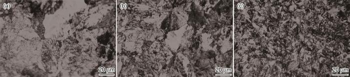
图5
三种试样的光学显微组织
Fig.5
OM metallographic structure of three samples (a) 1# sample; (b) 2# sample; (c) 3# sample
表4 三种试样的微观组织类型、片层大小、晶粒尺寸
Table 4
| Samples | Cooling process | Microstructure | Layers spacing / nm | Grain size / μm |
|---|---|---|---|---|
| 1# | Air cooling | Pearlite | 324.6 | 20.73 |
| 2# | Wind Cooling | Pearlite | 133.9 | 13.38 |
| 3# | 560oC-30 s | Pearlite | 105.9 | 7.90 |
图6
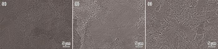
图6
三种试样的扫描电镜显微组织
Fig.6
SEM microscopic structure of three samples (a) 1# sample; (b) 2 # sample; (c) 3# sample
图7

图7
三种试样的珠光体片层
Fig.7
Pearlite layers of three samples (a) 1# sample; (b) 2# sample; (c) 3# sample
4 重轨钢疲劳裂纹尖端的应力-应变场
4.1 仿真模拟结果的线弹性分析
4.1.1 仿真模拟的应力场
将Franc3D中得到的模型导入Abaqus得到每一个循环次数的应力云图。实验中施加的力为8 kN,为了保证实验方案与模拟方案具有一致性,在Abaqus软件中也施加8 kN的载荷。如图8所示,为了研究疲劳裂纹的扩展,选用三种试样的疲劳裂纹长度分别为1、2、3 mm时的应力云图。可以看出,静载的应力和应变在距裂纹尖端较近的位置明显比裂纹其它位置高。其原因是,在材料设置时,在静载模型中只添加了弹塑性,没有设置最大主应力断裂条件,因此应力值的计算结果较高。根据弹塑性理论,裂纹位置固定时裂纹尖端的应变随着应力强度因子的增大而增大。
图8
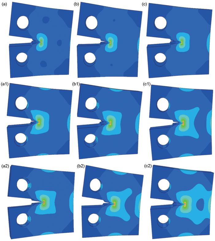
图8
1#、2#、3#试样的裂纹尖端应力云图
Fig.8
Stress nephogram of crack tip of 1#, 2#, 3 # specimen with different crack lengths (a, a1, a2) 1 mm; (b, b1, b2) 2 mm; (c, c1, c2) 3 mm
表5 疲劳裂纹尖端最大应力强度因子K
Table 5
| Crack lengths | 1 mm | 2 mm | 3 mm |
|---|---|---|---|
| 1# | 10.01 | 11.14 | 13.53 |
| 2# | 10.57 | 12.80 | 14.58 |
| 3# | 11.20 | 13.65 | 15.54 |
表6 三种试样的循环次数
Table 6
| Crack lengths | 1 mm | 2 mm | 3 mm |
|---|---|---|---|
| 1# | 181123 | 235634 | 281811 |
| 2# | 233184 | 362216 | 451513 |
| 3# | 373151 | 560202 | 706745 |
4.1.2 仿真模拟应变场分析
图9
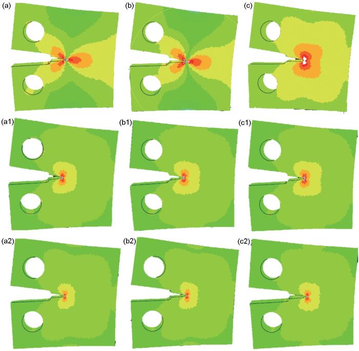
图9
1#、2#、3#试样的裂纹尖端应变云图
Fig.9
Strain nephogram of crack tip of 1#, 2#, 3# specimen with different crack lengths (a, a1, a2) 1 mm; (b, b1, b2) 2 mm; (c, c1, c2) 3 mm
图10

图10
长度不同的裂纹尖端应变场的变化
Fig.10
Variation of strain field at crack tip with different crack lengths
4.2 应变场的实验结果
表7列出了实验所得的疲劳数据,可以看出,在裂纹长度相同时,三种冷速的重轨钢试样中1#试样所需的循环次数最少,3#试样所需的循环次数最多,说明1#试样的疲劳性能最差,而3#试样的疲劳性能最好。在疲劳裂纹扩展实验过程中,用应变仪检测疲劳裂纹尖端应变场,得到了不同循环载荷作用下裂纹尖端应变场。图11给出了应变场的实验结果。可以看出,裂纹尖端的应变最显著,等效应变值最大,且随着疲劳裂纹长度的增大裂纹尖端的等效应变值随之增大,特别是裂纹长度为3 mm时三种冷速的重轨钢等效应变都达到最大值。裂纹长度相同时3#试样的等效应变区域小于2#试样小于1#试样,因为1#试样裂纹尖端附近的应力场强度较大,等效应变区域也比较大。
表7 三种试样的循环次数
Table 7
| Crack lengths | 1 mm | 2 mm | 3 mm |
|---|---|---|---|
| 1# | 8 × 10⁴ | 13 × 104 | 15 × 104 |
| 2# | 12 × 104 | 20 × 104 | 22 × 104 |
| 3# | 40 × 104 | 50 × 104 | 53 × 104 |
图11

图11
1#、2#、3#试样的裂纹尖端应变云图
Fig.11
Strain nephogram of crack tip of 1#, 2#, 3# specimen with different crack lengths (a, a1, a2) 1 mm; (b, b1, b2) 2 mm; (c, c1, c2) 3 mm
图12为裂纹尖端等效应变实验结果,可以看出,三种试样的裂纹长度相同时,3#试样裂纹尖端的等效应变值最小,1#试样裂纹尖端的等效应变值最大,其原因是,3#试样的晶粒尺寸小、片层间距小,且裂纹尖端的应力强度因子大,抵抗断裂的能力强,裂纹不易扩展。这也证明了,3#试样的疲劳性能最好而1#试样的疲劳性能最差。表8列出了模拟仿真结果等效应变与应变仪测量结果。可以看出,用两种方法得到的等效应变值都随着疲劳裂纹长度的增大而增大,且3#试样的最大等效应变值小于2#试样小于1#试样。随着冷速的递增裂纹长度相同时三种重轨钢裂纹尖端的等效应变值递减,其中裂纹长度为较长的3 mm时等效应变值模拟结果分别为0.074、0.067、0.055,而应变实验结果分别为0.082、0.064、0.058。这表明,模拟仿真结果与应变场实验结果最大误差为9.7%,两者有较好的一致性。
图12

表8 最大等效应变
Table 8
| Crack length | 1 mm | 2 mm | 3 mm | ||||||||
|---|---|---|---|---|---|---|---|---|---|---|---|
| Method and error rate | Simulation | Strain test | Error rate | Simulation | Strain test | Error rate | Simulation | Strain test | Error rate | ||
| 1# | 0.049 | 0.051 | 3.9% | 0.069 | 0.061 | 13.1% | 0.074 | 0.082 | 9.7% | ||
| 2# | 0.042 | 0.036 | 16.7% | 0.060 | 0.050 | 20% | 0.067 | 0.064 | 4.7% | ||
| 3# | 0.021 | 0.021 | 0 | 0.035 | 0.049 | 28.6% | 0.055 | 0.058 | 5.1% | ||
5 结论
(1) 随着冷速的递增在线轧态、在线热处理态、实验室热处理态重轨钢的珠光体片层间距递减;随着疲劳裂纹扩展其周围的应力场强和裂纹尖端的应力强度因子K增大,轧态的K最小,实验室热处理态的最大;随裂纹长度的增大同种试样裂纹尖端的应力强度因子值随之增大,应力场呈更加显著的“蝴蝶状”;在裂纹长度相同的条件下实验室热处理态重轨钢的应力强度因子K最大,表明细化珠光体片层有利于提高重轨钢的疲劳性能。
(2) 随着裂纹长度的增加,在线轧态、在线热处理态、实验室热处理态珠光体重轨钢裂纹尖端附近的等效应变区域不断增加。
(3) 随着冷速的递增,裂纹长度相同的三种重轨钢裂纹尖端等效应变值递减,可归因于实验室热处理态重轨钢的晶粒尺寸小、片层间距小,且裂纹尖端的应力强度因子大,抵抗断裂能力强,不易进行裂纹扩展,裂纹尖端的应变区域小,等效应变区域小同时也表明其疲劳性能好。模拟结果与测试结果的一致性较好,表明该模型的可靠性很高。
参考文献
Factors influencing fatigue crack initiation of rail for heavy haul railway
[J].
重载铁路钢轨疲劳裂纹萌生影响因素
[J].
Research progress on wheel/rail rolling contact fatigue of rail transit in China
[J].
中国轨道交通轮轨滚动接触疲劳研究进展
[J].
Effect of rail hardness on fatigue cracks initiation and rail wear
[J].
钢轨硬度对疲劳裂纹萌生和钢轨磨耗的影响
[J].
Effect of V and Si on microstructure and mechanical properties of medium-carbon pearlitic steels for wheel
[J].
The effect of V and Si on the microstructure and mechanical properties of medium-carbon pearlitic steels for wheel was studied by means of OM、SEM and TEM, as well as tensile and impact tests. The results showed that the austenite grain size, the pearlite colony size and interlamellar spacing were significantly refined by increasing V content, which also led to an increase in the volume fraction of proeutectoid ferrite of the steels. With the increasing of V content, the yield strength at room temperature and the impact toughness at -20℃were enhanced due to precipitation strengthening and grain refinement effects of VC. However, the tensile strength at room temperature was decreased due to the increasing of the soft phase, i.e., proeutectoid ferrite. The increase of Si content resulted in the great decrease of proeutectoid ferrite and the significant refinement of pearlite interlamellar spacing but the slight refinement of austenite grain size. Si addition also promoted the VC precipitation but had only a little influence. The yield- and tensile-strength were enhanced mainly by the effect of solid solution strengthening and the refinement of pearlite interlamellar spacing due to Si addition. The balance of strength and toughness in medium-carbon pearlite steels could be effectively optimized by microalloying with the combination of medium 0.07%-0.08%V(mass fraction) and relatively high 0.8%-0.9%Si (mass fraction).
V和Si对珠光体车轮钢显微组织和力学性能的影响规律
[J].
Formation mechanism and maintenance strategy of rail squat in Chinese high-speed railway
[J].
我国高速铁路钢轨隐伤形成机理及维护策略
[J].
Exploration on the unified model for fatigue properties prediction of metallic materials
[J].The fatigue of metallic materials can be divided into high-cycle fatigue (HCF) and low-cycle fatigue (LCF); the damage of these two types of fatigue is commonly evaluated through stress amplitude and strain amplitude of cyclic loading, respectively. The mismatch of the evaluation standards between HCF and LCF leads to difficulties in the design and selection of anti-fatigue materials. Under this condition, systematic researches on fatigue properties and microscopic damage mechanisms of HCF, LCF and extra-low-cycle fatigue (ELCF) for pure Cu and Cu-Al alloys were summarized in this work. On the bases of the experimental results, a three-dimensional fatigue model is proposed, which is simultaneously applicable to both the HCF and LCF properties. The model is built up in a three-dimensional coordinate system of stress amplitude-strain amplitude-fatigue life; it could be associated with the cyclic stress-strain (CSS) curve, S-N curve and E-N curve through the projection method, or be transformed into the Basquin equation, Coffin-Manson equation and hysteretic energy model under specific conditions. In this way, this generally applicable fatigue model helps provide a new viewpoint for the evaluation and optimization of fatigue properties based on the classical fatigue theories.
金属材料疲劳性能预测统一模型探索
[J].金属材料的疲劳可分为高周疲劳与低周疲劳,通常分别以应力幅与应变幅作为损伤参量;疲劳性能评价标准在高周与低周疲劳交界处的断层导致抗疲劳材料设计与选择的困难。本文通过对纯Cu及Cu-Al系列合金高周、低周(含超低周)疲劳性能与微观损伤机制的系统研究,提出了统一高周与低周性能的三维疲劳性能预测模型,并由其关键参数进一步提出了基于能量的疲劳性能统一评价标准。该模型建立在应力幅-应变幅-疲劳寿命三维坐标系下,可通过投影的方式获得循环应力-应变(CSS)曲线、应力-寿命(S-N)曲线与应变-寿命(E-N)曲线,模型函数在特定条件下也可转化为Basquin公式、Coffin-Manson公式与滞回能模型形式,从而在经典理论基础上为疲劳性能评价与优化问题提供了新的视角。
Prediction of rolling contact fatigue behavior in rails using crack initiation and growth models along with multibody simulations
[J].
Fatigue crack detection of heavy duty railway track based on decision fusion analysis
[J].
Crack propagation and rail surface spalling mechanism based on peridynamics
[J].
基于近场动力学的裂纹扩展及轨面剥离掉块成因机理
[J].
Study on wear behavior and debris particles emission characteristics induced by wheel-rail rolling contact under frequent start-stop conditions
[J].Rail transit vehicles are subject to frequent stops and starts near stations, the contact stress distribution between the wheel-rail interfaces become more complex during the process of acceleration and deceleration, which leads to unusual wheel-rail wear and debris behavior. An innovative wheel-rail rolling contact fatigue and wear test rig JD-DRCF/M is developed to carry out the cyclic acceleration and deceleration wear test for the wheel-rail rolling contact tribo-pairs and real-time monitoring of particle emission under frequent start-stop conditions, to understand the wear behavior and particle emission characteristics of the wheel-rail rolling contact interface near the station. The results showed that, the adhesion coefficient between wheel and rail is significantly affected by the acceleration <i>α</i><sub>r</sub>. With the increase of the acceleration <i>α</i><sub>r</sub>, the adhesion coefficient after the completion of the acceleration stage showed a trend of gradually decreased and then gradually rose. Moderate acceleration (<i>e.g.</i>, <i>α</i><sub>r</sub>=800 r·min<sup>-2</sup>) reduces the adhesion between wheel and rail interface, and mitigates the wear loss of wheel and rail effectively. The emission of inhalable particles (e.g<i>.</i>, 3.0 μm ≤ <i>d</i> ≤ 10.0 μm) is significantly increased under the start-stop condition (<i>i.e.</i>, the condition of acceleration). In especial, this phenomenon was more serious under the low acceleration condition (<i>e.g.</i>, <i>α</i><sub>r</sub>=400 r·min<sup>-2</sup>).
频繁启停工况下轮轨滚动接触磨损行为与磨屑颗粒排放特性研究
[J].轨道交通车辆在近站点附近须频繁启停,在加减速过程中轮轨界面接触应力分布变得更为复杂,从而引起轮轨磨耗和磨屑行为的改变。为深入了解近站点附近频繁启停工况下轮轨滚动接触界面的磨损特性与颗粒物排放行为,利用自行研制的JD-DRCF/M型轮轨滚动接触疲劳/磨损试验台开展了频繁启停工况下轮轨循环加减速磨损试验与颗粒物排放实时监测。结果表明,轮轨间黏着系数受加速度α<sub>r</sub>的影响显著;随着加速度α<sub>r</sub>的提高,加速阶段完成后的黏着系数依次呈现先下降后上升的趋势;适中的加速度(如α<sub>r</sub>=800 r·min<sup>-2</sup>)降低了轮轨间黏着,同时有效减缓了轮轨磨耗;启停工况(即有加速度时)大大提高了可吸入颗粒物(如3.0 ≤ d ≤ 10.0 μm)的排放浓度,尤其在较低的加速度(如400 r·min<sup>-2</sup>)工况下这种现象更为严重。
Prediction of fatigue crack propagation and fractography of rail steel
[J].
Influence of initial crack on fatigue crack propagation with mixed mode in U71Mn rail subsurface
[J].
Numerical method for predicting rail fatigue crack initiation with peridynamic theory
[J].
近场动力学框架下钢轨疲劳裂纹萌生预测的数值方法研究
[J].
: fatigue strength of railroad rail
[J].
Fatigue crack growth under non-proportional mixed mode I/III loading in rail and wheel steel
[J].
Influence of stress intensity factor on rail fatigue crack propagation by finite element method
[J].
Mixed mode II and III fatigue crack growth in a rail steel
[J].
Fatigue crack growth behavior of eutectoid steel rail
[J]. J.
Effect of quenching rate on fatigue crack growth of hypereutectoid rail steel
[J].
Effect of self-tempering on fatigue crack growth of heavy rail steel
[J].
自回火对重轨钢疲劳裂纹扩展行为的影响
[J].
Bending fatigue crack propagation behavior of U75V heavy rail steel
[J].In order to clarify the fatigue crack propagation behavior of pearlitic rail, the three-point bending fatigue crack propagation rate of U75V heavy rail steel in rolling state and heat treatment state was measured. The microstructure, lamella, fracture morphology and fatigue crack propagation trajectory of rail were observed by optical microscope, scanning electron microscope and EBSD. The results show that the average distance between fatigue striation of rolled and heat-treated rails is 252.5 nm and 215.4 nm, the fracture surface of rolled rail presents cleavage steps and river patterns, and the river patterns tend to merge.However, the fatigue fracture surface of the heat-treated rail presents a large number of cleavage steps, more microcracks and tear edges, and the river pattern is dominated by tributaries.The fatigue crack growth rate of heat-treated rail is much lower than that of rolled sample, and it is also slow to reach the stage of crack instability.The fatigue crack propagation mode of rolled and heat-treated rail is the mixed propagation mode of transgranular fracture and intergranular fracture dominated by transgranular fracture, the pearlite lamellae spacing of rolled and heat-treated rails is 272.2 nm and 148.4 nm respectively. The pearlite lamellae of heat-treated rails is fine and has various directions, while there are significant pearlite clusters in the heat-treated rail.There are many branch cracks and crack bridges in the crack growth path, which hinders the crack propagation in the heat-treated U75V heavy rail steel, which is an important reason why the fatigue crack propagation rate of the heat-treated rail is lower than that of the rolled rail.
U75V+重轨钢弯曲疲劳裂纹扩展行为
[J].为明确珠光体钢轨的疲劳裂纹扩展行为,测定U75V重轨钢轧态和热处理态两种条件下的三点弯曲疲劳裂纹扩展速率,采用光学显微镜、扫描电镜、EBSD对钢轨的微观组织、片层、断口形貌及裂纹扩展轨迹进行观察。结果表明:轧态和热处理态钢轨的疲劳辉纹平均间距分别为253,215 nm,轧态钢轨的疲劳断口呈现解理台阶与河流花样形貌,且河流花样趋于合并,而热处理态钢轨的疲劳断口呈现大量的解理台阶及较多的微裂纹和撕裂棱,河流花样以支流为主;热处理态钢轨的疲劳裂纹扩展速率远低于轧态,到达裂纹失稳阶段也较滞后;轧态和热处理态钢轨的疲劳裂纹扩展都是以穿晶断裂为主的穿晶断裂和沿晶断裂混合扩展方式进行,轧态和热处理态钢轨的珠光体片层间距分别为272,148 nm,其中热处理态钢轨的珠光体片层细密且方向多样,存在显著的珠光体团簇,裂纹扩展轨迹中出现较多的分支裂纹和裂纹桥接现象,对扩展起到阻碍作用,是热处理态钢轨抗疲劳裂纹扩展能力优于轧态的重要原因。
Optimization of quenching process and fatigue crack growth behavior of microalloyed rail
[J].In order to quantitative analysis of the correlation between microalloying with quenching process and crack growth, to find a way to correct the phenomenon of self-tempering during rail quenching, through the fatigue crack growth test of GGX-G heavy rail steel and self-developed and designed microalloyed element heavy rail experimental steel after quenching and cooling rate of 8℃/s and quenching and cooling rate of 8℃/s and self -tempering, the results show that under the condition of no heat treatment, the fatigue life of the experimental steel is better than that of GGX-G steel for 0.11 million times; after 8℃/s cold speed and 8℃/s cold speed self-tempering process, it has been increased from 0.77 million times to 1.07 million times, and self-tempering does not affect the fatigue life of the steel, and still has good fatigue performance; after quenching, there is a slow propagation zone in zone II of the experimental steel, and the △<i>K</i> range of the experimental steel is higher after self-tempering, the microalloyed rail has excellent resistance to the reduction of fatigue properties caused by self-tempering; the experimental steels after quenching process all meet the requirements of national standard, and the fatigue fracture surface of 8℃/s quenching cooling rate is similar to that of 8℃/s quenching cooling rate, which also indicates that self-tempering has little effect on fatigue properties of experimental steels, it has strong self-tempering resistance. The addition of microalloyed elements not only improves the fatigue performance of quenched rail, but also corrects the effect of self-tempering on rail performance.
微合金化钢轨淬火工艺的优化及其疲劳裂纹扩展行为研究
[J].
