齿轮钢的力学性能优良,广泛用于制造汽车、工程机械、航空航天设备的重要零部件。进行喷丸[1 ] 、渗碳[2 ] 、渗氮[3 ] 等表面处理,可提高齿轮钢的使用寿命、疲劳强度和表面耐磨性。但是,低于传统疲劳极限的问题还频频发生[4 ,5 ] 。为了提高机械产品的长期安全性,需要研究长寿命状态下齿轮钢的疲劳特性和提出评估强度的方法。
经表面强化处理的齿轮钢其S-N 曲线具有独特的“阶梯状”或“双线性”[5 ~7 ] ,即失效模式由表面向内部转变。疲劳破坏构件中的裂纹,通常由冶金过程中的非金属夹杂物诱发[8 ,9 ] 。疲劳断口中近似圆形的鱼眼区,是内部疲劳破坏的典型特征。与鱼眼内区域相比,在断裂起源处以夹杂为中心的白亮区域呈现出粗糙的颗粒状形态。Murakami等[10 ] 将这片区域命名为“光学暗区(Optical dark area, ODA)”,Shiozawa等[11 ] 将该区域命名为“颗粒亮面区(Granular bright facets, GBF)”,Sakai等[12 ] 将其命名为“细颗粒区(Fine granular area, FGA)”。FGA的形成消耗了90%以上的超高周疲劳寿命[11 ,13 ] ,表明夹杂尺寸和FGA特征尺寸是有限材料疲劳性能的重要因素。
随着对零部件长期有效性要求的提高,材料的强度问题备受国内外学者关注,相继提出了一些预测疲劳强度的模型。Murakami等[14 ] 基于维氏硬度和夹杂尺寸提出了疲劳极限预测模型,Wang等[15 ] 改进Murakami的模型提出了一种考虑夹杂尺寸或微观缺陷的疲劳强度预测模型。丁明超等[16 ] 结合Murakami理论提出了一种基于微观划痕的疲劳强度预测模型。Choi等[17 ] 基于计算的最大缺陷尺寸提出了较为保守的疲劳极限预测模型。孙振铎等[18 ] 基于极值分布函数构建了一种与夹杂尺寸相关的疲劳强度预测模型。邓海龙等[19 ] 基于累积损伤法提出了变应力比下夹杂-FAG-鱼眼型失效疲劳强度预测模型。但是,这些预测模型较少虑及失效机理。鉴于此,本文对渗碳Cr-Ni齿轮钢进行超高周疲劳实验研究应力比为0和0.3的渗碳Cr-Ni齿轮钢的疲劳特性。基于累积损伤理论和位错能量法并结合渗碳Cr-Ni齿轮钢的FGA形成机理和夹杂最大评估尺寸,建立两种渗碳Cr-Ni齿轮钢的疲劳强度预测模型,并结合FGA尺寸和夹杂尺寸的比值与夹杂应力强度因子及应力比之间的关系对其进行修正。
1 实验方法
实验用Cr-Ni齿轮钢的化学成分,列于表1 。先将Cr-Ni齿轮钢的原始棒料加工成具有一定加工余量的沙漏形试样,并为满足性能要求对其表面进行渗碳处理。对渗碳试样进行热处理,工艺为:840℃的真空中油淬45 min+160℃空气中低温回火90 min。为了去除表面划痕,用360#~2000#砂纸沿轴线方向打磨,最终试样的长度为152 mm,最小横截面直径为4.5 mm,沙漏圆弧半径为60 mm,圆弧表面粗糙度为0.32。
在上述试样的最小截面处截取金相试样,用砂纸打磨和抛光后使用含4%乙醇硝酸溶液在室温下侵蚀,用带有能谱仪的扫描电镜(Scanning electron microscope, SEM) 观测金相试样的渗碳层和基体的微观组织。
基于连续刚度测量方法,使用纳米压头G200测量渗碳Cr-Ni齿轮钢的渗碳层和基体区域的微观硬度。基于GB/T228.1-2010的相关标准,使用MTS 809试验机和圆形横截面试样进行室温拉伸实验,拉伸速率为5 mm/min,拉伸试样的总长度为100.00 mm,中间平行部分直径为4.50 mm,平行长度为30.00 mm,平行部分与夹持部分采用圆弧过渡,圆弧半径为4.00 mm。
使用轴向加载高频疲劳测试机(QBG-100) 进行疲劳试样的室温超高周疲劳实验,频率为100 Hz,施加的应力比R 分别为0和0.3。应力比为0时施加的最大应力幅为650 MPa,最小应力幅为500 MPa;应力比为0.3时施加的最大应力幅为507.5 MPa,最小应力幅为437.5 MPa。试样完全断裂或循环次数达到1×10⁸ 次时终止试验。共得到16个有效数据,其中应力比为0的样本11个,应力比为0.3的5个。用扫描电镜观测所有疲劳失效试样的断口表面。
2 结果和分析
2.1 渗碳层和基体的微观组及性能
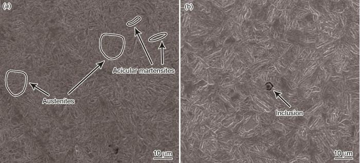
试样的渗碳层和基体的微观组织,如图1 a和b所示。可以看出,渗碳Cr-Ni齿轮钢渗碳层和基体的微观组织有很大不同,渗碳层中的微观组织主要是针状马氏体和残余奥氏体,而在基体中的微观组织主要为板条马氏体。此外,在渗碳层和基体中均可以发现非金属夹杂。
图1
图1
渗碳Cr-Ni齿轮钢的微观组织
Fig.1
Microstructure of carburized Cr-Ni gear steel (a) carburized, (b) base
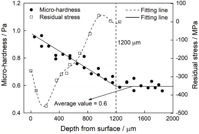
Cr-Ni齿轮钢的渗碳层和基体区域的维氏硬度与距离表面深部的关系,如图2 中的实线所示。
图2 表明,试样表面维氏硬度值最大,约为0.97 Pa。随着距离试样表面深度的增加维氏硬度呈现出减小的趋势,在距离表面深度达到1200 μm后,硬度值趋于稳定。据此可知,渗碳Cr-Ni齿轮钢的渗碳层深度约为1200 μm,基体硬度约为0.6 Pa。基于线性拟合,维氏硬度(HV)与深度(x )的关系可表达为
H V = 0.97 - 3.08 × 10 - 4 x x < 1200 H V = 0.6 x ≥ 1200 (1)
基于TEC4000 x射线衍射系统得到渗碳Cr-Ni齿轮钢从表面到基体区域的残余应力值,如图2 中虚线所示。试样表面的残余应力值为-268 MPa。随着深度的增加,残余应力值呈现出先减小后增加最后接近0的趋势。当距离表面深度超过1200 μm后,残余应力消失,进一步说明试样渗碳层深度约为1200 μm。随着深度的变化残余应力呈现出一定的规律性,基于多项式拟合得到残余应力(σ r )与距离表面深度(x )之间的关系
σ r = - 267.23 - 0.89 x - 0.018 x 2 + 1.73 × 10 - 4 x 3 - 5.73 × 10 - 7 x 4 + 9.57 × 10 - 10 x 5 - 8.58 × 10 - 13 x 6 + 3.59 × 10 - 16 x 7 - 7.31 × 10 - 20 x 8 (2)
图2
图2
微观硬度和残余应力与深度的关系
Fig.2
Relationship between micro-hardness and residual stress and depth
渗碳Cr-Ni齿轮钢的抗拉强度σ b 约为1780 MPa。
2.2 S-N 曲线
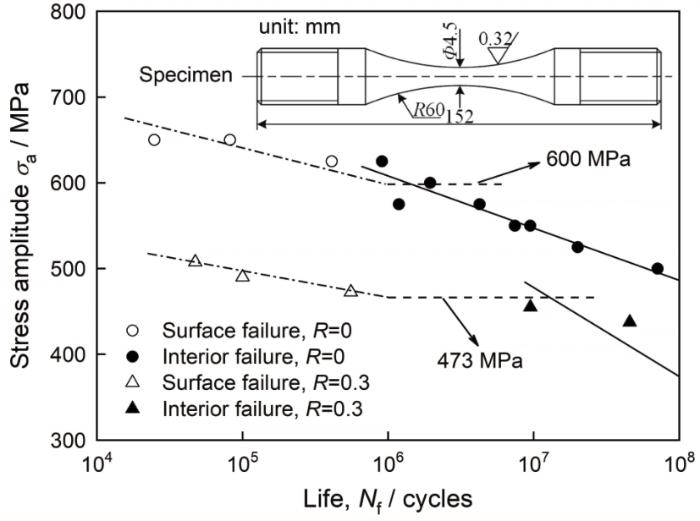
图3 给出了渗碳Cr-Ni齿轮钢在应力比R 为0和0.3时的应力幅与疲劳寿命的关系。在两种应力比下,没有出现传统的疲劳极限。在同一应力比下,随着疲劳寿命的增加疲劳强度呈现减小的趋势。在相同寿命下,R =0.3的疲劳强度都小于R =0的疲劳强度。根据裂纹起裂位置和疲劳寿命分布,大致可将每个应力比下的数据点分为两部分:一部分是高于1×10⁶ 个循环次数的内部失效(即当失效形式全部表现为内部失效时的疲劳寿命),另一部分是低于1×10⁶ 个循环次数的表面失效。换言之,随着疲劳寿命的增加,试样的失效形式由表面失效转变为内部失效。基于线性拟合可得Cr-Ni齿轮钢的S-N 曲线。S-N 曲线呈现出“双线性”特性,表面失效和内部失效分别由点划线和直线表示。此外,将1×10⁶ 个循环次数对应的疲劳强度定义为渗碳Cr-Ni齿轮钢的表面疲劳极限,如图3 中的虚线所示。因此,应力比为0和0.3的表面疲劳极限分别为600和473 MPa。本文将循环次数为1×10⁸ 时的疲劳强度定义为渗碳Cr-Ni齿轮钢的内部疲劳极限,故应力比为0和0.3的疲劳极限分别为490和374 MPa。显然,疲劳极限随应力比的增加而降低。
图3
图3
应力比为0和0.3时渗碳Cr-Ni齿轮钢的S-N 曲线
Fig.3
S-N curves of carburized Cr-Ni gear steel for stress ratios of 0 and 0.3
2.3 疲劳断口的形貌
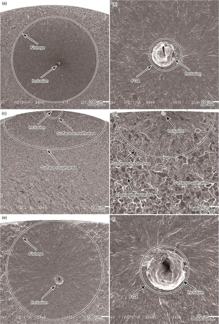
图4 给出了所有疲劳失效样本断口的表面形貌。根据裂纹萌生位置和失效断口形貌,可将疲劳失效形式分为两种:一种是带有FGA的内部失效(图4 a、b、e和f),另一种是有SSA (Surface smooth area,表面光滑区)的表面失效(图4 c和4 d)。对比两种应力比下内部疲劳断口可知,试样均由夹杂-FGA-fisheye诱发疲劳失效。应力比为0.3时更难观测到FGA,且随着应力比的增加尺寸有减小的趋势。无论是内部失效还是表面失效,在鱼眼和SSA的区域均可见非金属夹杂。因此可以断定,非金属夹杂诱发了疲劳裂纹的萌生。
图4
图4
典型断口表面的形貌
Fig.4
Observation of typical fracture surfaces (a) fisheye (σ a = 575 MPa, N f = 4254700 cycles, R = 0), (b) inclusion with FGA (σ a = 575 MPa, N f = 4254700 cycles, R = 0); (c) surface failure (σ a = 650 MPa, N f = 82100 cycles, R = 0), (d) inclusion (σ a = 650 MPa, N f = 82100 cycles, R = 0); (e) fisheye (σ a = 455 MPa, N f = 9494900 cycles, R = 0.3), (f) inclusion with FGA (σ a = 455 MPa, N f = 9494900 cycles, R = 0.3)
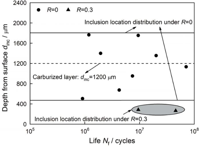
对于夹杂引发的内部失效,夹杂位置距离试样表面的深度如图5 所示。应力比为0时引发失效的夹杂一部分位于基体中,另一部分位于渗碳层中;应力比到达0.3时引发失效的夹杂全部位于渗碳层中。换言之,随着应力比的增加诱发裂纹萌生的夹杂越来越靠近表面。造成这一现象的原因,是最大应力、残余应力和高硬度之间的相互作用。当施加的最大应力较小时渗碳层中的残余应力和高强度抑制了裂纹的萌生和扩展,导致疲劳裂纹由基体中的夹杂诱发。当施加的最大应力较大时最大应力克服了渗碳层中残余应力和高强度的影响,使渗碳层中的夹杂诱发裂纹并导致最终失效。
图5
图5
夹杂距离表面的深度
Fig.5
Depth of inclusion from surface
对于夹杂引发的表面失效,在外加载荷和表面残余应力的共同作用下夹杂周围引发的应力集中导致裂纹扩展。因此,在疲劳失效断口表面可观察到以夹杂为中心的光滑区域,称为表面光滑区(Surface smooth area, SSA);在SSA之外裂纹迅速扩展形成了放射形裂纹组成的椭圆形状的粗糙区域,称为表面粗糙区(Surface rough area, SRA),如图4 c和4 d所示。
2.4 裂纹的特征尺寸
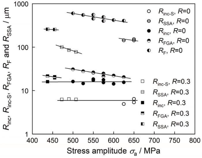
使用ImageJ图形测量软件,获得所有观测的SEM断口图的疲劳裂纹特征尺寸。因为可将疲劳裂纹形成的区域近似为圆形,用R inc-S 、R SSA 、R inc 、R FGA 和R F 表示表面夹杂、SSA、内部夹杂、FGA和鱼眼的半径。图6 给出了各裂纹特征尺寸和疲劳强度的关系。显然,引发失效的夹杂尺寸与施加的应力比和应力幅无关。随着疲劳强度的提高,除夹杂外两种应力比下各裂纹的特征尺寸均呈现减小的趋势。
图6
图6
裂纹特征尺寸与σ a 的关系
Fig.6
Relationships between crack sizesand σ a
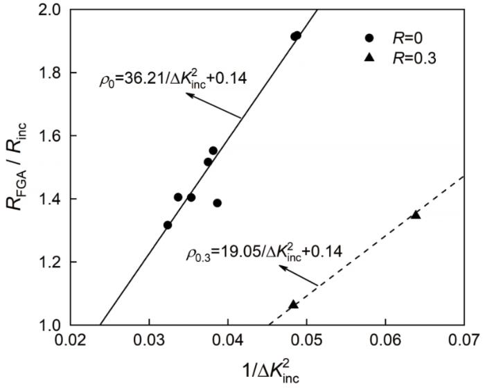
研究表明,FGA尺寸与夹杂尺寸的比值正比于1/ΔK i n c 2 [20 ] ,其中ΔK inc 为夹杂应力强度因子范围(ΔK inc = 2/ π·Δσ a ·(πR inc )0.5 )。文献[21 ]讨论了应力强度因子ΔK 。虑及应力比影响的关系式为
ρ = R F G A R i n c = a + b R Δ K i n c - 2 + c (3)
式中ρ 为FGA尺寸与夹杂尺寸的比值,R 为应力比,a 、b 和c 均为常数。将夹杂应力强度因子公式带入 式(3)可得
ρ = R F G A R i n c = a + b R 2 π Δ σ a π R i n c × 10 - 6 - 2 + c (4)
将应力比为0和0.3的疲劳试验数据带入 式(4),基于最小二乘法可得a 、b 和c 的值分别为36.21、-57.21和0.14。拟合结果在图7 中给出,可见FGA尺寸与夹杂尺寸的比值是线性的。
图7
图7
R FGA /R inc 与1/ΔK i n c 2
Fig.7
Relationship between R FGA /R inc and 1/ΔK i n c 2
2.5 内部失效机理
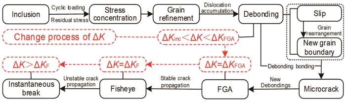
基于断口微观形貌和应力强度因子可得长寿命区内部失效机理示意图,如图8 所示。残余应力、外加载荷以及夹杂与基体弹性模量不匹配的共同作用在夹杂周围形成局部应力集中,从而使晶粒细化。在循环载荷作用下夹杂周围的应力强度因子大于ΔK inc ,晶粒滑移使夹杂周围的位错堆积[22 ] 。晶粒重新排列到新晶界而形成由亚晶粒组成的细晶粒层[23 ] ,这一过程称为脱粘。在循环荷载的进一步作用下细晶粒层与粗基体之间的边界处出现越来越多新的脱粘,最终使脱粘相互结合形成微裂纹。随着裂纹的萌生细晶粒层的面积不断扩大,ΔK 值达到FGA应力强度因子ΔK FGA 时形成了细颗粒区(FGA)。在此过程中,随着微裂纹的进一步结合脱粘继续产生并在FGA中形成新的细晶粒层。因此,FGA表面比较粗糙,FGA的形成消耗了大部分疲劳寿命。当ΔK 大于ΔK FGA 时疲劳裂纹进入稳定扩展阶段,结束时ΔK 到达鱼眼应力强度因子ΔK F 而形成所谓鱼眼。由于在裂纹稳定扩展阶段不存在脱粘现象,鱼眼的表面形貌比FGA更为光滑。ΔK 大于ΔK F 时多种滑移模式共同作用,使裂纹扩展加快。裂纹扩展到临界尺寸时试件剩余有效截面不足以承受施加的载荷时,于是材料瞬间断裂。
图8
图8
内部失效机理
Fig.8
Interior failure mechanism
2.6 疲劳强度预测模型的构建
2.6.1 基于累积损伤理论的疲劳强度预测模型构建(模型I)
长寿命区疲劳断口均存在FGA,FGA的形成消耗了90%以上的疲劳寿命。因此,FGA的尺寸是预测疲劳强度的重要参数。由于FGA内疲劳裂纹萌生的原因循环加载,因此可以假设每次循环加载都使试件产生微量损伤。因此可得
R N = R i n c ∏ n = 1 N ( 1 + p n ) ≥ R F G A (5)
其中RN 为第n 次加载后的损伤区半径,pn 为第n 次加载后的损伤区半径增量与第n -1次加载后的损伤区半径的比值。为了简化计算,使用与pn 和疲劳寿命相关的变量p
( 1 + p ) = ∏ n = 1 N ( 1 + p n ) 1 N (6)
R N = R i n c ( 1 + p ) N ≥ R F G A (7)
N f ≈ 1 l g ( 1 + p ) l g R F G A R i n c (8)
由于在长寿命区的疲劳寿命值较大,p 值接近于0。因此 式(8)可改写为
N f ≈ 1 p l g R F G A R i n c (9)
传统的疲劳强度,与材料的抗拉强度有关[24 ] 。而渗碳齿轮钢中的残余应力会抑制或促进裂纹的萌生。因此,残余应力是影响渗碳Cr-Ni合金钢疲劳寿命的重要因素。p 与最大应力σ max 、抗拉强度σ b 、残余应力σ r 之间的关系为
p = σ b σ m a x + σ r (10)
为了使数学模型更精确,引入拟合参数m 和n 。将 式(10)代入 式(9),可得
l g N f = m σ b σ m a x + σ r + l g l g R F G A R i n c + n (11)
使用疲劳使用得到的数据,可得σ b /(σ max +σ r )+lg(lg(R FGA /R inc ))与lgN f 之间的关系,如图9 所示。可以看出,拟合曲线想效果很好。根据最小二乘法,可得各应力比的m 和n 的值。R =0时m 0 和n 0 分别为3.71和3.41,应力比为0.3时m 0.3 和n 0.3 分别为2.63和5.21。
图9
图9
σ b /(σ max +σ r )+lg(lg(R FGA /R inc ))与lgN f 的关系
Fig.9
Relationship between σ b /(σ max +σ r )+lg(lg(R FGA /R inc )) and lgN f
根据最大应力、应力幅值与应力比的关系,可将渗碳Cr-Ni齿轮钢的疲劳强度预测模型表示为
σ a = 1 - R 2 m σ b l g N f - m l g l g R F G A R i n c - n - σ r (12)
2.6.2 基于位错能量法的内部疲劳强度预测模型构建(模型II)
在长寿命状态,夹杂物和界面在较低应力下强度足够大也不会发生断裂,加载一定周期后塑性流动在基体中积聚。非金属夹杂物抑制位错运动,因此在夹杂物周围逐渐形成椭圆形滑移带。夹杂物边缘的位错堆积,使夹杂物周围萌生裂纹。在这种情况下可将偶极子中储存的能量等价于单位面积的断裂能,从而得到使疲劳裂纹萌生的加载循环次数。假设滑移带中所有位错偶极子都使裂纹萌生起裂,可提出与内部夹杂物开裂有关的裂纹萌生寿命模型[25 ]
N f = μ m μ m + μ i n c μ i n c h h + l 2 4 W S Δ τ - 2 τ f 2 1 R i n c (13)
其中μ inc 为夹杂物的剪切模量,μ m 为基体的剪切模量,W s 为沿滑移带单位面积的比断裂能,Δτ 为局部剪应力范围,τf 为临界剪应力。l 和h 分别为滑移带的长半轴和短半轴。取l 值等于晶粒尺寸的一半。其中E 与μ 的关系为
μ = E 2 + 2 v (14)
式中μ 为剪切模量,E 为弹性模量,v 为泊松比。 式(13)中的Δτ 和τ f 可分别表示为
Δ τ = 2 Δ σ 3 (15)
τ f = 2 σ w 3 (16)
式中Δσ 为应力范围,σ w 为疲劳极限。本文将疲劳极限定义为循环次数为1×10⁸ 时的疲劳强度。最近的研究表明,并不是所有的位错都对裂纹萌生起作用,而裂纹萌生时的裂纹尺寸与导致裂纹形成的位错数量有关[26 ] 。因此,可将W S 的值修正为
W S = μ m c 0.005 h 2 l 2 (17)
式中c 为裂纹尺寸。将式(15)、(16)和(17)代入 式(13)可得
N 1 2 = μ m μ m + μ i n c 0.005 μ i n c 1 2 3 h 2 μ m 1 2 2 2 l h + l σ a - σ w c R i n c 1 2 (18)
为了提高模型的精度,将疲劳寿命的指数改为拟合参数α (0<α <1)[27 ]
N α = μ m μ m + μ i n c 0.005 μ i n c 1 2 3 h 2 μ m 1 2 2 2 l h + l σ a - σ w c R i n c 1 2 (19)
本文假定在长寿命状态下椭圆滑移带扩展到整个FGA,于是得
N f α = μ m μ m + μ i n c 0.005 μ i n c 1 2 3 h F G A 2 μ m 1 2 2 2 l F G A h F G A + l F G A σ a - σ w c R i n c 1 2 (20)
其中l FGA 和h FGA 分别为FGA的长度和宽度。由于FGA的形状近似于圆形,l FGA 近似等于h FGA 。进一步整理则基于位错能量法的疲劳强度预测模型为
σ a = 3 μ m N f - α 4 2 c R i n c 1 2 μ m + μ i n c 0.005 μ i n c 1 2 + σ w (21)
将应力比为0和0.3的试验数据带入 式(21),基于最大继承法可得应力比为0时α 0 的值为0.59,应力比为0.3时α 0.3 的值为0.50。
2.6.3 l FGA -S-N 曲线的建立和预测强度对比
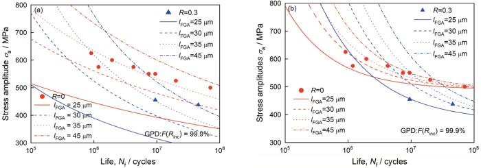
所建立的疲劳强度预测模型包括夹杂尺寸和FGA尺寸,而夹杂尺寸与齿轮钢的冶炼工艺密切有关。因此,渗碳Cr-Ni齿轮钢的疲劳强度预测模型在很大程度上取决于FGA尺寸。文献[21 ]表明,使用GPD(Generalized pareto distribution)函数预测夹杂尺寸更为准确。将GPD函数预测的最大夹杂尺寸(失效概率为99.9%时的夹杂物尺寸)代入 式(20)中,基于疲劳累积损伤的不同FGA尺寸的内部疲劳强度预测模型为
σ a = m σ b l g N f - m l g l g l F G A R i n c - G P D , 99.9 % - n - σ r 1 - R 2 (22)
其中R inc-GPD,99.9% 为失效概率为99.9%时的GPD函数评估的夹杂尺寸。同理,基于位错能量法不同FGA尺寸的内部疲劳强度预测模型为
σ a = 3 μ m N f - α 4 2 R F G A - R i n c - G P D , 99.9 % R i n c - G P D , 99.9 % 1 2 μ m + μ i n c 0.005 μ i n c 1 2 + σ w (23)
基于 式(22)和(23),最大夹杂尺寸时不同FGA尺寸下渗碳Cr-Ni齿轮钢的S-N 曲线如图10 所示。
图10
图10
基于GPD函数建立的l FGA -S-N 曲线
Fig.10
Established l FGA -S-N curves by using GPD function; (a) cumulative damage method; (b) dislocation energy method
在相同的应力比和一定的疲劳寿命下,两种方法预测的疲劳强度均随FGA尺寸的增大而增大。相对于 式(22)建立的长寿命状态下不同FGA尺寸下的内部S-N 曲线, 式(23)的模型更加紧凑,即基于位错能量法建立的疲劳强度预测模型更加可靠。
此外,在构件疲劳失效前不能得到FGA尺寸,因此将 式(4)中FGA尺寸与夹杂尺寸的比值带入 式(22)和(23),最后在不同应力比下修正后的渗碳Cr-Ni齿轮钢的疲劳强度预测模型为
σ a = 1 - R 2 m σ b l g N f - m l g l g ρ - n - σ r (24)
σ a = 3 μ m N - α 4 2 ρ - 1 1 2 μ m + μ i n c 0.005 μ i n c 1 2 + σ w (25)
式中ρ 为FGA尺寸与夹杂尺寸的比值。基于 式(24)和(25)可得渗碳Cr-Ni齿轮钢在GPD函数下最大夹杂尺寸时的疲劳强度,如表2 所示。由此可见,在夹杂尺寸的累积概率为99.9%时两种模型预测的疲劳强度均比较保守,模型I预测的疲劳强度比模型II预测的偏小。相对于实验侧测出的疲劳强度,模型II预测的疲劳强度更加精确。因此,本文建立的疲劳强度预测模型均能很好地评估渗碳Cr-Ni齿轮钢的疲劳强度,而基于位错能量法建立的疲劳强度预测模型可以更准确地评估渗碳Cr-Ni齿轮钢的疲劳强度。
3 结论
(1) 在应力比分别为0和0.3的加载条件下,根据裂纹的特征尺寸可建立FGA尺寸与夹杂尺寸的比值与夹杂应力强度因子和应力比的关系。
(2) 基于累积损伤法和位错能量法并结合FGA形成过程和最大夹杂评估尺寸,可分别建立两种渗碳Cr-Ni齿轮钢疲劳强度预测模型并构建不同裂纹特征尺寸的S-N 曲线。
(3) 根据FGA尺寸与夹杂尺寸的比值与夹杂应力强度因子与应力比之间的关系,可修正所提出两种疲劳强度预测模型。这两种疲劳强度预测模型都比较保守,而基于位错能量法建立的疲劳强度预测模型精度较高。
参考文献
View Option
[1]
Takahashi K Osedo H Suzuki T et al Fatigue strength improvement of an aluminum alloy with a crack-like surface defect using shot peening and cavitation peening
[J]. Eng. Fract. Mech. , 2018 , 193 : 151
DOI
URL
[本文引用: 1]
[2]
Xiao N Hui W J Zhang Y J et al High cycle fatigue behavior of a low carbon alloy steel: the influence of vacuum carburizing treatment
[J]. Eng. Fail. Anal. , 2020 , 109 : 104215
DOI
URL
[本文引用: 1]
[3]
Zhang T Y Wu J S Jin L et al Enhancing the mechanical and anticorrosion properties of 316L stainless steel via a cathodic plasma electrolytic nitriding treatment with added PEG
[J]. J. Mater. Sci. Technol. , 2019 , 35 (11 ): 2630
DOI
[本文引用: 1]
A cathodic plasma electrolytic nitriding (CPEN) treatment with a urea aqueous solution was performed on 316L stainless steel to rapidly improve its surface properties in this work. Test results show that the PEG2000 macromolecules increased the nitriding energy via enhancing the ability to bond the produced gas film to the metal/electrolyte interface. The cross-sectional morphologies indicate that a thick nitrided layer was obtained when the urea concentration was 543 g l-1, corresponding to a Vickers hardness 450 HV0.1, which was 3.5 times larger than that of the substrate. The nitrided layer mainly contained expanded austenite (γN), oxides and iron nitrides (e.g., Fe3O4 and FeN0.076). In terms of its performance, coefficient of friction (COF) of the nitride layer decreased to nearly two-thirds that of the untreated layer, and the passivation current densities of the nitrided sample in a 3.5% NaCl solution decreased by an order of magnitude compared to that of the substrate. Therefore, the approach presented herein provides an attractive way to modify the effect of CPEN in a urea aqueous solution.
[4]
Hou F Li J K Xie S X et al Very high cycle fatigue properties of CrMoW rotor steel at high-temperature
[J]. Chin. J. Mater. Res. , 2016 , 30 (7 ): 481
DOI
[本文引用: 1]
The fatigue properties of CrMoW rotor steel were investigated by a high temperature ultrasonic fatigue system. Fatigue tests of CrMoW rotor steel up to 1×10¹⁰ cycles had been conducted at room temperature and 600℃ respectively. Results reveal that the type of S-N curves present continuously descending at room temperature and 600℃. Fatigue fracture occured over 109 cycles. Fractograph of specimens show that Crack initiate mainly from the surface for the specimens that fatigue life is less than 1×10⁷ cycles, but crack initiate mostly from inclusions for those that fatigue life is greater than 1×10⁷ cycles at room temperature. It is found that crack can also initiate at inclusions, but the modes of crack initiation do not play a decisive role for the fatigue life at high temperature. Threshold values of fatigue crack growth obtained by measuring the size of fisheye are 3.4 MPam1/2 and 1.0 MPam1/2 at room temperature and 600℃ respectively.
侯 方 , 李久楷 , 谢少雄 等 CrMoW转子钢的高温超高周疲劳性能
[J]. 材料研究学报 , 2016 , 30 (7 ): 481
[本文引用: 1]
[5]
Li C Li W Cai L et al Microstructure based cracking behavior and life assessment of titanium alloy under very-high-cycle fatigue with elevated temperatures
[J]. Int. J. Fatigue , 2022 , 161 : 106914
DOI
URL
[本文引用: 2]
[6]
Han S W Yang X G Shi D Q et al Microstructure-sensitive modeling of competing failure mode between surface and internal nucleation in high cycle fatigue
[J]. Int. J. Plasticity , 2020 , 126 : 102622
DOI
URL
[7]
Kong W W Yuan C Zhang B N Investigations on cyclic deformation behaviors and corresponding failure modes of a Ni-Based superalloy
[J]. Mater. Sci. Eng. , 2020 , 791A : 139775
[本文引用: 1]
[8]
Lei L Liang Y L Jiang Y et al Effect of quench rate on the high cycle fatigue property of 60Si2CrVAT spring steels
[J]. Chin. J. Mater. Res. , 2017 , 31 (1 ): 65
[本文引用: 1]
雷 磊 , 梁益龙 , 姜 云 等 淬火冷却速率对60Si2CrVAT弹簧钢高周疲劳性能的影响
[J]. 材料研究学报 , 2017 , 31 (1 ): 65
[本文引用: 1]
[9]
Huang Y Q Wang D Lu Y Z et al Fatigue crack initiation behavior at intermediate temperature under high stress amplitude for single crystal superalloy DD413
[J]. Chin. J. Mater. Res. , 2021 , 35 (7 ): 510
DOI
[本文引用: 1]
The fatigue crack initiation behavior of a single crystal superalloy DD413 was investigated under high stress amplitude at intermediate temperature. The fracture surfaces and longitudinal section morphologies of the test specimens were characterized by scanning electron microscope (SEM). It was found that fatigue cracks mostly initiate from the cracked blocky carbides on the surface as well as the cracked skeleton-like carbides at subsurface. All the carbides on the surface of testing specimen crack due to the combined effect of oxidation and cyclic loading. Besides, at the subsurface of testing specimen, the carbides located on the propagation path of a micro-crack can crack as a result of oxidation and cyclic loading. The micro-crack connected to the surface in the specimen is the transportation channel of oxygen for the oxidation of the carbides at the subsurface. Carbides cracked and the micro-crack initiated at the early stage of fatigue, which induced the final failure.
黄亚奇 , 王 栋 , 卢玉章 等 第一代单晶高温合金中温高应力幅下的疲劳裂纹萌生行为
[J]. 材料研究学报 , 2021 , 35 (7 ): 510
DOI
[本文引用: 1]
通过应力控制的疲劳实验探究第一代镍基单晶高温合金DD413在中温(760℃)高应力幅下的疲劳裂纹萌生行为,并使用扫描电子显微镜观察和表征了疲劳样品的断口形貌和纵截面的显微组织。结果表明:在高应力幅条件下,疲劳裂纹主要萌生于表面开裂的块状碳化物和次表面开裂的骨架状碳化物。在疲劳过程中,氧化和循环加载的共同作用使样品表面的碳化物都发生了开裂。在样品的次表面,只有位于表面微裂纹扩展路径上的碳化物发生开裂,其原因也与氧化和循环加载有关。样品表面产生的微裂纹,是次表面碳化物发生氧化所需氧气的运输通道。在疲劳的早期阶段碳化物即发生开裂并产生微裂纹,最终使样品发生疲劳断裂。
[10]
Murakami Y Yokoyama N N Nagata J Mechanism of fatigue failure in ultralong life regime
[J]. Fatigue Fract. Eng. Mater. Struct. , 2002 , 25 (8-9 ): 735
DOI
URL
[本文引用: 1]
[11]
Shiozawa K Morii Y Nishino S et al Subsurface crack initiation and propagation mechanism in high-strength steel in a very high cycle fatigue regime
[J]. Int. J. Fat. , 2006 , 28 (11 ): 1521
DOI
URL
[本文引用: 2]
[12]
Sakai T Oguma N Morikawa A Microscopic and nanoscopic observations of metallurgical structures around inclusions at interior crack initiation site for a bearing steel in very high-cycle fatigue
[J]. Fatigue Fract. Eng. Mater. Struct. , 2015 , 38 (11 ): 1305
DOI
URL
[本文引用: 1]
[13]
Hong Y S Lei Z Q Sun C Q et al Propensities of crack interior initiation and early growth for very-high-cycle fatigue of high strength steels
[J]. Int. J. Fatigue , 2014 , 58 : 144
DOI
URL
[本文引用: 1]
[14]
Murakami Y Endo M Effects of defects, inclusions and inhomogeneities on fatigue strength
[J]. Int. J. Fatigue , 1994 , 16 (3 ): 163
DOI
URL
[本文引用: 1]
[15]
Wang Q Y Berard J Y Dubarre A et al Gigacycle fatigue of ferrous alloys
[J]. Fatigue Fract. Eng. Mater. Struct. , 1999 , 22 (8 ): 667
DOI
URL
[本文引用: 1]
[16]
Ding M C Zhang Y L Xian H W et al Fatigue strength prediction based on micro scratches
[J]. J. Northeastern Univ. (Nat. Sci.) , 2020 , 41 (5 ): 693
[本文引用: 1]
丁明超 , 张元良 , 咸宏伟 等 基于微观划痕的疲劳强度预测
[J]. 东北大学学报(自然科学版) , 2020 , 41 (5 ): 693
[本文引用: 1]
[17]
Choi B H Song S H Prediction of fatigue limit of induction surface hardened 1.05Cr–0.23Mo steel alloy using extreme value statistics
[J]. J. Mater. Sci. , 2005 , 40 (20 ): 5427
DOI
URL
[本文引用: 1]
[18]
Sun Z D Hou D B Li Z Y Prediction for fatigue strength and distribution features of inclusion of carburized Cr-Mn steel
[J]. Ordnance Mater. Sci. Eng. , 2021 , 44 (1 ): 98
[本文引用: 1]
孙振铎 , 侯东勃 , 李志远 渗碳Cr-Mn钢的夹杂分布特性及疲劳强度预测
[J]. 兵器材料科学与工程 , 2021 , 44 (1 ): 98
[本文引用: 1]
[19]
Deng H L Liu H Liu Q C et al Fatigue strength prediction of carburized 12Cr steel alloy: effects of evaluation of maximum crack sizes and residual stress distribution
[J]. Fatigue Fract. Eng. Mater. Struct. , 2020 , 43 (2 ): 342
DOI
URL
[本文引用: 1]
[20]
Li Y D Zhang L L Zhang C et al Ultra-long life fatigue behavior of SUJ2 bearing steel
[J]. J. Mater. Eng. , 2016 , 44 (8 ): 85
[本文引用: 1]
李永德 , 张莉莉 , 张 冲 等 SUJ2轴承钢超长寿命疲劳行为研究
[J]. 材料工程 , 2016 , 44 (8 ): 85
[本文引用: 1]
[21]
Deng H L Liu B Guo Y et al Effect of local equivalent stress on fatigue life prediction of carburized Cr-Ni alloy steel based on evaluation of maximum crack sizes
[J]. Eng. Fract. Mech. , 2021 , 248 : 107718
DOI
URL
[本文引用: 2]
[22]
Liu Z Y Liu Y J Liu P et al Effects of grain size on fatigue properties of K492 superalloy
[J]. Chin. J. Mater. Res. , 2018 , 32 (11 ): 834
[本文引用: 1]
刘志远 , 刘勇军 , 刘 鹏 等 晶粒度对K492高温合金疲劳性能的影响
[J]. 材料研究学报 , 2018 , 32 (11 ): 834
[本文引用: 1]
[23]
Gao N Li W Sun R et al A fatigue assessment approach involving small crack growth modelling for structural alloy steels with interior fracture behavior
[J]. Eng. Fract. Mech. , 2018 , 204 : 198
DOI
URL
[本文引用: 1]
[24]
Sakai T Review and prospects for current studies on very high cycle fatigue of metallic materials for machine structural use
[J]. J. Solid Mech. Mater. Eng. , 2009 , 3 (3 ): 425
DOI
URL
[本文引用: 1]
[25]
Tanaka K Mura T A theory of fatigue crack initiation at inclusions
[J]. Metall . Trans., 1982 , 13A(1 ) : 117
[本文引用: 1]
[26]
Chan K S A microstructure-based fatigue-crack-initiation model
[J]. Metall. Mater. Trans. , 2003 , 34A : 43
[本文引用: 1]
[27]
Cheng A S Laird C A quick and simple method for orienting cubic single crystals from Laue back-reflection photographs
[J]. J. Appl. Cryst. , 1982 , 15 : 137
DOI
URL
[本文引用: 1]
Fatigue strength improvement of an aluminum alloy with a crack-like surface defect using shot peening and cavitation peening
1
2018
... 齿轮钢的力学性能优良,广泛用于制造汽车、工程机械、航空航天设备的重要零部件.进行喷丸[1 ] 、渗碳[2 ] 、渗氮[3 ] 等表面处理,可提高齿轮钢的使用寿命、疲劳强度和表面耐磨性.但是,低于传统疲劳极限的问题还频频发生[4 ,5 ] .为了提高机械产品的长期安全性,需要研究长寿命状态下齿轮钢的疲劳特性和提出评估强度的方法. ...
High cycle fatigue behavior of a low carbon alloy steel: the influence of vacuum carburizing treatment
1
2020
... 齿轮钢的力学性能优良,广泛用于制造汽车、工程机械、航空航天设备的重要零部件.进行喷丸[1 ] 、渗碳[2 ] 、渗氮[3 ] 等表面处理,可提高齿轮钢的使用寿命、疲劳强度和表面耐磨性.但是,低于传统疲劳极限的问题还频频发生[4 ,5 ] .为了提高机械产品的长期安全性,需要研究长寿命状态下齿轮钢的疲劳特性和提出评估强度的方法. ...
Enhancing the mechanical and anticorrosion properties of 316L stainless steel via a cathodic plasma electrolytic nitriding treatment with added PEG
1
2019
... 齿轮钢的力学性能优良,广泛用于制造汽车、工程机械、航空航天设备的重要零部件.进行喷丸[1 ] 、渗碳[2 ] 、渗氮[3 ] 等表面处理,可提高齿轮钢的使用寿命、疲劳强度和表面耐磨性.但是,低于传统疲劳极限的问题还频频发生[4 ,5 ] .为了提高机械产品的长期安全性,需要研究长寿命状态下齿轮钢的疲劳特性和提出评估强度的方法. ...
CrMoW转子钢的高温超高周疲劳性能
1
2016
... 齿轮钢的力学性能优良,广泛用于制造汽车、工程机械、航空航天设备的重要零部件.进行喷丸[1 ] 、渗碳[2 ] 、渗氮[3 ] 等表面处理,可提高齿轮钢的使用寿命、疲劳强度和表面耐磨性.但是,低于传统疲劳极限的问题还频频发生[4 ,5 ] .为了提高机械产品的长期安全性,需要研究长寿命状态下齿轮钢的疲劳特性和提出评估强度的方法. ...
CrMoW转子钢的高温超高周疲劳性能
1
2016
... 齿轮钢的力学性能优良,广泛用于制造汽车、工程机械、航空航天设备的重要零部件.进行喷丸[1 ] 、渗碳[2 ] 、渗氮[3 ] 等表面处理,可提高齿轮钢的使用寿命、疲劳强度和表面耐磨性.但是,低于传统疲劳极限的问题还频频发生[4 ,5 ] .为了提高机械产品的长期安全性,需要研究长寿命状态下齿轮钢的疲劳特性和提出评估强度的方法. ...
Microstructure based cracking behavior and life assessment of titanium alloy under very-high-cycle fatigue with elevated temperatures
2
2022
... 齿轮钢的力学性能优良,广泛用于制造汽车、工程机械、航空航天设备的重要零部件.进行喷丸[1 ] 、渗碳[2 ] 、渗氮[3 ] 等表面处理,可提高齿轮钢的使用寿命、疲劳强度和表面耐磨性.但是,低于传统疲劳极限的问题还频频发生[4 ,5 ] .为了提高机械产品的长期安全性,需要研究长寿命状态下齿轮钢的疲劳特性和提出评估强度的方法. ...
... 经表面强化处理的齿轮钢其S-N 曲线具有独特的“阶梯状”或“双线性”[5 ~7 ] ,即失效模式由表面向内部转变.疲劳破坏构件中的裂纹,通常由冶金过程中的非金属夹杂物诱发[8 ,9 ] .疲劳断口中近似圆形的鱼眼区,是内部疲劳破坏的典型特征.与鱼眼内区域相比,在断裂起源处以夹杂为中心的白亮区域呈现出粗糙的颗粒状形态.Murakami等[10 ] 将这片区域命名为“光学暗区(Optical dark area, ODA)”,Shiozawa等[11 ] 将该区域命名为“颗粒亮面区(Granular bright facets, GBF)”,Sakai等[12 ] 将其命名为“细颗粒区(Fine granular area, FGA)”.FGA的形成消耗了90%以上的超高周疲劳寿命[11 ,13 ] ,表明夹杂尺寸和FGA特征尺寸是有限材料疲劳性能的重要因素. ...
Microstructure-sensitive modeling of competing failure mode between surface and internal nucleation in high cycle fatigue
0
2020
Investigations on cyclic deformation behaviors and corresponding failure modes of a Ni-Based superalloy
1
2020
... 经表面强化处理的齿轮钢其S-N 曲线具有独特的“阶梯状”或“双线性”[5 ~7 ] ,即失效模式由表面向内部转变.疲劳破坏构件中的裂纹,通常由冶金过程中的非金属夹杂物诱发[8 ,9 ] .疲劳断口中近似圆形的鱼眼区,是内部疲劳破坏的典型特征.与鱼眼内区域相比,在断裂起源处以夹杂为中心的白亮区域呈现出粗糙的颗粒状形态.Murakami等[10 ] 将这片区域命名为“光学暗区(Optical dark area, ODA)”,Shiozawa等[11 ] 将该区域命名为“颗粒亮面区(Granular bright facets, GBF)”,Sakai等[12 ] 将其命名为“细颗粒区(Fine granular area, FGA)”.FGA的形成消耗了90%以上的超高周疲劳寿命[11 ,13 ] ,表明夹杂尺寸和FGA特征尺寸是有限材料疲劳性能的重要因素. ...
淬火冷却速率对60Si2CrVAT弹簧钢高周疲劳性能的影响
1
2017
... 经表面强化处理的齿轮钢其S-N 曲线具有独特的“阶梯状”或“双线性”[5 ~7 ] ,即失效模式由表面向内部转变.疲劳破坏构件中的裂纹,通常由冶金过程中的非金属夹杂物诱发[8 ,9 ] .疲劳断口中近似圆形的鱼眼区,是内部疲劳破坏的典型特征.与鱼眼内区域相比,在断裂起源处以夹杂为中心的白亮区域呈现出粗糙的颗粒状形态.Murakami等[10 ] 将这片区域命名为“光学暗区(Optical dark area, ODA)”,Shiozawa等[11 ] 将该区域命名为“颗粒亮面区(Granular bright facets, GBF)”,Sakai等[12 ] 将其命名为“细颗粒区(Fine granular area, FGA)”.FGA的形成消耗了90%以上的超高周疲劳寿命[11 ,13 ] ,表明夹杂尺寸和FGA特征尺寸是有限材料疲劳性能的重要因素. ...
第一代单晶高温合金中温高应力幅下的疲劳裂纹萌生行为
1
2021
... 经表面强化处理的齿轮钢其S-N 曲线具有独特的“阶梯状”或“双线性”[5 ~7 ] ,即失效模式由表面向内部转变.疲劳破坏构件中的裂纹,通常由冶金过程中的非金属夹杂物诱发[8 ,9 ] .疲劳断口中近似圆形的鱼眼区,是内部疲劳破坏的典型特征.与鱼眼内区域相比,在断裂起源处以夹杂为中心的白亮区域呈现出粗糙的颗粒状形态.Murakami等[10 ] 将这片区域命名为“光学暗区(Optical dark area, ODA)”,Shiozawa等[11 ] 将该区域命名为“颗粒亮面区(Granular bright facets, GBF)”,Sakai等[12 ] 将其命名为“细颗粒区(Fine granular area, FGA)”.FGA的形成消耗了90%以上的超高周疲劳寿命[11 ,13 ] ,表明夹杂尺寸和FGA特征尺寸是有限材料疲劳性能的重要因素. ...
Mechanism of fatigue failure in ultralong life regime
1
2002
... 经表面强化处理的齿轮钢其S-N 曲线具有独特的“阶梯状”或“双线性”[5 ~7 ] ,即失效模式由表面向内部转变.疲劳破坏构件中的裂纹,通常由冶金过程中的非金属夹杂物诱发[8 ,9 ] .疲劳断口中近似圆形的鱼眼区,是内部疲劳破坏的典型特征.与鱼眼内区域相比,在断裂起源处以夹杂为中心的白亮区域呈现出粗糙的颗粒状形态.Murakami等[10 ] 将这片区域命名为“光学暗区(Optical dark area, ODA)”,Shiozawa等[11 ] 将该区域命名为“颗粒亮面区(Granular bright facets, GBF)”,Sakai等[12 ] 将其命名为“细颗粒区(Fine granular area, FGA)”.FGA的形成消耗了90%以上的超高周疲劳寿命[11 ,13 ] ,表明夹杂尺寸和FGA特征尺寸是有限材料疲劳性能的重要因素. ...
Subsurface crack initiation and propagation mechanism in high-strength steel in a very high cycle fatigue regime
2
2006
... 经表面强化处理的齿轮钢其S-N 曲线具有独特的“阶梯状”或“双线性”[5 ~7 ] ,即失效模式由表面向内部转变.疲劳破坏构件中的裂纹,通常由冶金过程中的非金属夹杂物诱发[8 ,9 ] .疲劳断口中近似圆形的鱼眼区,是内部疲劳破坏的典型特征.与鱼眼内区域相比,在断裂起源处以夹杂为中心的白亮区域呈现出粗糙的颗粒状形态.Murakami等[10 ] 将这片区域命名为“光学暗区(Optical dark area, ODA)”,Shiozawa等[11 ] 将该区域命名为“颗粒亮面区(Granular bright facets, GBF)”,Sakai等[12 ] 将其命名为“细颗粒区(Fine granular area, FGA)”.FGA的形成消耗了90%以上的超高周疲劳寿命[11 ,13 ] ,表明夹杂尺寸和FGA特征尺寸是有限材料疲劳性能的重要因素. ...
... [11 ,13 ],表明夹杂尺寸和FGA特征尺寸是有限材料疲劳性能的重要因素. ...
Microscopic and nanoscopic observations of metallurgical structures around inclusions at interior crack initiation site for a bearing steel in very high-cycle fatigue
1
2015
... 经表面强化处理的齿轮钢其S-N 曲线具有独特的“阶梯状”或“双线性”[5 ~7 ] ,即失效模式由表面向内部转变.疲劳破坏构件中的裂纹,通常由冶金过程中的非金属夹杂物诱发[8 ,9 ] .疲劳断口中近似圆形的鱼眼区,是内部疲劳破坏的典型特征.与鱼眼内区域相比,在断裂起源处以夹杂为中心的白亮区域呈现出粗糙的颗粒状形态.Murakami等[10 ] 将这片区域命名为“光学暗区(Optical dark area, ODA)”,Shiozawa等[11 ] 将该区域命名为“颗粒亮面区(Granular bright facets, GBF)”,Sakai等[12 ] 将其命名为“细颗粒区(Fine granular area, FGA)”.FGA的形成消耗了90%以上的超高周疲劳寿命[11 ,13 ] ,表明夹杂尺寸和FGA特征尺寸是有限材料疲劳性能的重要因素. ...
Propensities of crack interior initiation and early growth for very-high-cycle fatigue of high strength steels
1
2014
... 经表面强化处理的齿轮钢其S-N 曲线具有独特的“阶梯状”或“双线性”[5 ~7 ] ,即失效模式由表面向内部转变.疲劳破坏构件中的裂纹,通常由冶金过程中的非金属夹杂物诱发[8 ,9 ] .疲劳断口中近似圆形的鱼眼区,是内部疲劳破坏的典型特征.与鱼眼内区域相比,在断裂起源处以夹杂为中心的白亮区域呈现出粗糙的颗粒状形态.Murakami等[10 ] 将这片区域命名为“光学暗区(Optical dark area, ODA)”,Shiozawa等[11 ] 将该区域命名为“颗粒亮面区(Granular bright facets, GBF)”,Sakai等[12 ] 将其命名为“细颗粒区(Fine granular area, FGA)”.FGA的形成消耗了90%以上的超高周疲劳寿命[11 ,13 ] ,表明夹杂尺寸和FGA特征尺寸是有限材料疲劳性能的重要因素. ...
Effects of defects, inclusions and inhomogeneities on fatigue strength
1
1994
... 随着对零部件长期有效性要求的提高,材料的强度问题备受国内外学者关注,相继提出了一些预测疲劳强度的模型.Murakami等[14 ] 基于维氏硬度和夹杂尺寸提出了疲劳极限预测模型,Wang等[15 ] 改进Murakami的模型提出了一种考虑夹杂尺寸或微观缺陷的疲劳强度预测模型.丁明超等[16 ] 结合Murakami理论提出了一种基于微观划痕的疲劳强度预测模型.Choi等[17 ] 基于计算的最大缺陷尺寸提出了较为保守的疲劳极限预测模型.孙振铎等[18 ] 基于极值分布函数构建了一种与夹杂尺寸相关的疲劳强度预测模型.邓海龙等[19 ] 基于累积损伤法提出了变应力比下夹杂-FAG-鱼眼型失效疲劳强度预测模型.但是,这些预测模型较少虑及失效机理.鉴于此,本文对渗碳Cr-Ni齿轮钢进行超高周疲劳实验研究应力比为0和0.3的渗碳Cr-Ni齿轮钢的疲劳特性.基于累积损伤理论和位错能量法并结合渗碳Cr-Ni齿轮钢的FGA形成机理和夹杂最大评估尺寸,建立两种渗碳Cr-Ni齿轮钢的疲劳强度预测模型,并结合FGA尺寸和夹杂尺寸的比值与夹杂应力强度因子及应力比之间的关系对其进行修正. ...
Gigacycle fatigue of ferrous alloys
1
1999
... 随着对零部件长期有效性要求的提高,材料的强度问题备受国内外学者关注,相继提出了一些预测疲劳强度的模型.Murakami等[14 ] 基于维氏硬度和夹杂尺寸提出了疲劳极限预测模型,Wang等[15 ] 改进Murakami的模型提出了一种考虑夹杂尺寸或微观缺陷的疲劳强度预测模型.丁明超等[16 ] 结合Murakami理论提出了一种基于微观划痕的疲劳强度预测模型.Choi等[17 ] 基于计算的最大缺陷尺寸提出了较为保守的疲劳极限预测模型.孙振铎等[18 ] 基于极值分布函数构建了一种与夹杂尺寸相关的疲劳强度预测模型.邓海龙等[19 ] 基于累积损伤法提出了变应力比下夹杂-FAG-鱼眼型失效疲劳强度预测模型.但是,这些预测模型较少虑及失效机理.鉴于此,本文对渗碳Cr-Ni齿轮钢进行超高周疲劳实验研究应力比为0和0.3的渗碳Cr-Ni齿轮钢的疲劳特性.基于累积损伤理论和位错能量法并结合渗碳Cr-Ni齿轮钢的FGA形成机理和夹杂最大评估尺寸,建立两种渗碳Cr-Ni齿轮钢的疲劳强度预测模型,并结合FGA尺寸和夹杂尺寸的比值与夹杂应力强度因子及应力比之间的关系对其进行修正. ...
基于微观划痕的疲劳强度预测
1
2020
... 随着对零部件长期有效性要求的提高,材料的强度问题备受国内外学者关注,相继提出了一些预测疲劳强度的模型.Murakami等[14 ] 基于维氏硬度和夹杂尺寸提出了疲劳极限预测模型,Wang等[15 ] 改进Murakami的模型提出了一种考虑夹杂尺寸或微观缺陷的疲劳强度预测模型.丁明超等[16 ] 结合Murakami理论提出了一种基于微观划痕的疲劳强度预测模型.Choi等[17 ] 基于计算的最大缺陷尺寸提出了较为保守的疲劳极限预测模型.孙振铎等[18 ] 基于极值分布函数构建了一种与夹杂尺寸相关的疲劳强度预测模型.邓海龙等[19 ] 基于累积损伤法提出了变应力比下夹杂-FAG-鱼眼型失效疲劳强度预测模型.但是,这些预测模型较少虑及失效机理.鉴于此,本文对渗碳Cr-Ni齿轮钢进行超高周疲劳实验研究应力比为0和0.3的渗碳Cr-Ni齿轮钢的疲劳特性.基于累积损伤理论和位错能量法并结合渗碳Cr-Ni齿轮钢的FGA形成机理和夹杂最大评估尺寸,建立两种渗碳Cr-Ni齿轮钢的疲劳强度预测模型,并结合FGA尺寸和夹杂尺寸的比值与夹杂应力强度因子及应力比之间的关系对其进行修正. ...
Prediction of fatigue limit of induction surface hardened 1.05Cr–0.23Mo steel alloy using extreme value statistics
1
2005
... 随着对零部件长期有效性要求的提高,材料的强度问题备受国内外学者关注,相继提出了一些预测疲劳强度的模型.Murakami等[14 ] 基于维氏硬度和夹杂尺寸提出了疲劳极限预测模型,Wang等[15 ] 改进Murakami的模型提出了一种考虑夹杂尺寸或微观缺陷的疲劳强度预测模型.丁明超等[16 ] 结合Murakami理论提出了一种基于微观划痕的疲劳强度预测模型.Choi等[17 ] 基于计算的最大缺陷尺寸提出了较为保守的疲劳极限预测模型.孙振铎等[18 ] 基于极值分布函数构建了一种与夹杂尺寸相关的疲劳强度预测模型.邓海龙等[19 ] 基于累积损伤法提出了变应力比下夹杂-FAG-鱼眼型失效疲劳强度预测模型.但是,这些预测模型较少虑及失效机理.鉴于此,本文对渗碳Cr-Ni齿轮钢进行超高周疲劳实验研究应力比为0和0.3的渗碳Cr-Ni齿轮钢的疲劳特性.基于累积损伤理论和位错能量法并结合渗碳Cr-Ni齿轮钢的FGA形成机理和夹杂最大评估尺寸,建立两种渗碳Cr-Ni齿轮钢的疲劳强度预测模型,并结合FGA尺寸和夹杂尺寸的比值与夹杂应力强度因子及应力比之间的关系对其进行修正. ...
渗碳Cr-Mn钢的夹杂分布特性及疲劳强度预测
1
2021
... 随着对零部件长期有效性要求的提高,材料的强度问题备受国内外学者关注,相继提出了一些预测疲劳强度的模型.Murakami等[14 ] 基于维氏硬度和夹杂尺寸提出了疲劳极限预测模型,Wang等[15 ] 改进Murakami的模型提出了一种考虑夹杂尺寸或微观缺陷的疲劳强度预测模型.丁明超等[16 ] 结合Murakami理论提出了一种基于微观划痕的疲劳强度预测模型.Choi等[17 ] 基于计算的最大缺陷尺寸提出了较为保守的疲劳极限预测模型.孙振铎等[18 ] 基于极值分布函数构建了一种与夹杂尺寸相关的疲劳强度预测模型.邓海龙等[19 ] 基于累积损伤法提出了变应力比下夹杂-FAG-鱼眼型失效疲劳强度预测模型.但是,这些预测模型较少虑及失效机理.鉴于此,本文对渗碳Cr-Ni齿轮钢进行超高周疲劳实验研究应力比为0和0.3的渗碳Cr-Ni齿轮钢的疲劳特性.基于累积损伤理论和位错能量法并结合渗碳Cr-Ni齿轮钢的FGA形成机理和夹杂最大评估尺寸,建立两种渗碳Cr-Ni齿轮钢的疲劳强度预测模型,并结合FGA尺寸和夹杂尺寸的比值与夹杂应力强度因子及应力比之间的关系对其进行修正. ...
Fatigue strength prediction of carburized 12Cr steel alloy: effects of evaluation of maximum crack sizes and residual stress distribution
1
2020
... 随着对零部件长期有效性要求的提高,材料的强度问题备受国内外学者关注,相继提出了一些预测疲劳强度的模型.Murakami等[14 ] 基于维氏硬度和夹杂尺寸提出了疲劳极限预测模型,Wang等[15 ] 改进Murakami的模型提出了一种考虑夹杂尺寸或微观缺陷的疲劳强度预测模型.丁明超等[16 ] 结合Murakami理论提出了一种基于微观划痕的疲劳强度预测模型.Choi等[17 ] 基于计算的最大缺陷尺寸提出了较为保守的疲劳极限预测模型.孙振铎等[18 ] 基于极值分布函数构建了一种与夹杂尺寸相关的疲劳强度预测模型.邓海龙等[19 ] 基于累积损伤法提出了变应力比下夹杂-FAG-鱼眼型失效疲劳强度预测模型.但是,这些预测模型较少虑及失效机理.鉴于此,本文对渗碳Cr-Ni齿轮钢进行超高周疲劳实验研究应力比为0和0.3的渗碳Cr-Ni齿轮钢的疲劳特性.基于累积损伤理论和位错能量法并结合渗碳Cr-Ni齿轮钢的FGA形成机理和夹杂最大评估尺寸,建立两种渗碳Cr-Ni齿轮钢的疲劳强度预测模型,并结合FGA尺寸和夹杂尺寸的比值与夹杂应力强度因子及应力比之间的关系对其进行修正. ...
SUJ2轴承钢超长寿命疲劳行为研究
1
2016
... 研究表明,FGA尺寸与夹杂尺寸的比值正比于1/ΔK i n c 2 [20 ] ,其中ΔK inc 为夹杂应力强度因子范围(ΔK inc = 2/ π·Δσ a ·(πR inc )0.5 ).文献[21 ]讨论了应力强度因子ΔK .虑及应力比影响的关系式为 ...
SUJ2轴承钢超长寿命疲劳行为研究
1
2016
... 研究表明,FGA尺寸与夹杂尺寸的比值正比于1/ΔK i n c 2 [20 ] ,其中ΔK inc 为夹杂应力强度因子范围(ΔK inc = 2/ π·Δσ a ·(πR inc )0.5 ).文献[21 ]讨论了应力强度因子ΔK .虑及应力比影响的关系式为 ...
Effect of local equivalent stress on fatigue life prediction of carburized Cr-Ni alloy steel based on evaluation of maximum crack sizes
2
2021
... 研究表明,FGA尺寸与夹杂尺寸的比值正比于1/ΔK i n c 2 [20 ] ,其中ΔK inc 为夹杂应力强度因子范围(ΔK inc = 2/ π·Δσ a ·(πR inc )0.5 ).文献[21 ]讨论了应力强度因子ΔK .虑及应力比影响的关系式为 ...
... 所建立的疲劳强度预测模型包括夹杂尺寸和FGA尺寸,而夹杂尺寸与齿轮钢的冶炼工艺密切有关.因此,渗碳Cr-Ni齿轮钢的疲劳强度预测模型在很大程度上取决于FGA尺寸.文献[21 ]表明,使用GPD(Generalized pareto distribution)函数预测夹杂尺寸更为准确.将GPD函数预测的最大夹杂尺寸(失效概率为99.9%时的夹杂物尺寸)代入 式(20) 中,基于疲劳累积损伤的不同FGA尺寸的内部疲劳强度预测模型为 ...
晶粒度对K492高温合金疲劳性能的影响
1
2018
... 基于断口微观形貌和应力强度因子可得长寿命区内部失效机理示意图,如图8 所示.残余应力、外加载荷以及夹杂与基体弹性模量不匹配的共同作用在夹杂周围形成局部应力集中,从而使晶粒细化.在循环载荷作用下夹杂周围的应力强度因子大于ΔK inc ,晶粒滑移使夹杂周围的位错堆积[22 ] .晶粒重新排列到新晶界而形成由亚晶粒组成的细晶粒层[23 ] ,这一过程称为脱粘.在循环荷载的进一步作用下细晶粒层与粗基体之间的边界处出现越来越多新的脱粘,最终使脱粘相互结合形成微裂纹.随着裂纹的萌生细晶粒层的面积不断扩大,ΔK 值达到FGA应力强度因子ΔK FGA 时形成了细颗粒区(FGA).在此过程中,随着微裂纹的进一步结合脱粘继续产生并在FGA中形成新的细晶粒层.因此,FGA表面比较粗糙,FGA的形成消耗了大部分疲劳寿命.当ΔK 大于ΔK FGA 时疲劳裂纹进入稳定扩展阶段,结束时ΔK 到达鱼眼应力强度因子ΔK F 而形成所谓鱼眼.由于在裂纹稳定扩展阶段不存在脱粘现象,鱼眼的表面形貌比FGA更为光滑.ΔK 大于ΔK F 时多种滑移模式共同作用,使裂纹扩展加快.裂纹扩展到临界尺寸时试件剩余有效截面不足以承受施加的载荷时,于是材料瞬间断裂. ...
A fatigue assessment approach involving small crack growth modelling for structural alloy steels with interior fracture behavior
1
2018
... 基于断口微观形貌和应力强度因子可得长寿命区内部失效机理示意图,如图8 所示.残余应力、外加载荷以及夹杂与基体弹性模量不匹配的共同作用在夹杂周围形成局部应力集中,从而使晶粒细化.在循环载荷作用下夹杂周围的应力强度因子大于ΔK inc ,晶粒滑移使夹杂周围的位错堆积[22 ] .晶粒重新排列到新晶界而形成由亚晶粒组成的细晶粒层[23 ] ,这一过程称为脱粘.在循环荷载的进一步作用下细晶粒层与粗基体之间的边界处出现越来越多新的脱粘,最终使脱粘相互结合形成微裂纹.随着裂纹的萌生细晶粒层的面积不断扩大,ΔK 值达到FGA应力强度因子ΔK FGA 时形成了细颗粒区(FGA).在此过程中,随着微裂纹的进一步结合脱粘继续产生并在FGA中形成新的细晶粒层.因此,FGA表面比较粗糙,FGA的形成消耗了大部分疲劳寿命.当ΔK 大于ΔK FGA 时疲劳裂纹进入稳定扩展阶段,结束时ΔK 到达鱼眼应力强度因子ΔK F 而形成所谓鱼眼.由于在裂纹稳定扩展阶段不存在脱粘现象,鱼眼的表面形貌比FGA更为光滑.ΔK 大于ΔK F 时多种滑移模式共同作用,使裂纹扩展加快.裂纹扩展到临界尺寸时试件剩余有效截面不足以承受施加的载荷时,于是材料瞬间断裂. ...
Review and prospects for current studies on very high cycle fatigue of metallic materials for machine structural use
1
2009
... 传统的疲劳强度,与材料的抗拉强度有关[24 ] .而渗碳齿轮钢中的残余应力会抑制或促进裂纹的萌生.因此,残余应力是影响渗碳Cr-Ni合金钢疲劳寿命的重要因素.p 与最大应力σ max 、抗拉强度σ b 、残余应力σ r 之间的关系为 ...
A theory of fatigue crack initiation at inclusions
1
1982
... 在长寿命状态,夹杂物和界面在较低应力下强度足够大也不会发生断裂,加载一定周期后塑性流动在基体中积聚.非金属夹杂物抑制位错运动,因此在夹杂物周围逐渐形成椭圆形滑移带.夹杂物边缘的位错堆积,使夹杂物周围萌生裂纹.在这种情况下可将偶极子中储存的能量等价于单位面积的断裂能,从而得到使疲劳裂纹萌生的加载循环次数.假设滑移带中所有位错偶极子都使裂纹萌生起裂,可提出与内部夹杂物开裂有关的裂纹萌生寿命模型[25 ] ...
A microstructure-based fatigue-crack-initiation model
1
2003
... 式中Δσ 为应力范围,σ w 为疲劳极限.本文将疲劳极限定义为循环次数为1×10⁸ 时的疲劳强度.最近的研究表明,并不是所有的位错都对裂纹萌生起作用,而裂纹萌生时的裂纹尺寸与导致裂纹形成的位错数量有关[26 ] .因此,可将W S 的值修正为 ...
A quick and simple method for orienting cubic single crystals from Laue back-reflection photographs
1
1982
... 为了提高模型的精度,将疲劳寿命的指数改为拟合参数α (0<α <1)[27 ] ...


