


管道在输运过程中因流动冲刷造成的腐蚀泄露事故频繁发生,油气管道输运过程中的安全、高效运转日益引起人们的重视[1]。当管道内表面由于流速、介质浓度等因素的影响而出现局部腐蚀坑等管道缺陷或者腐蚀破损时,流体流经此处的流速会发生急剧变化,导致局部微湍流的形成[2,3]。微湍流的存在将导致管道缺陷处腐蚀介质浓度差异及较大流体力学参数变化,加速腐蚀介质与基体接触频率,同时会导致局部存在的较大壁面剪切力,增加管线钢破损失效概率[4, 5],管道泄露的风险系数也随之增加。油气田管道输运过程中包含各种腐蚀性介质,例如Cl-,硫化物,有机酸和一些溶解气体(如CO2)。这些腐蚀性介质也严重威胁着管道的完整性[6, 7]。CO2溶于水形成的碳酸(H2CO3)对管线钢电化学腐蚀的阴极反应过程具有较大影响[8]。碳酸(H2CO3)和乙酸(HAc)水解产生的氢离子(H+)用作去极化剂,以加速阳极的溶解并达到电化学平衡[9,10]。同时,局部凹陷区较大的湍流动能会导致腐蚀介质加速与基体的接触,引起缺陷区局部腐蚀介质浓度较大差异,基体本身溶解机制及表面产物膜的沉积速率也会发生变化,从而可能引发更严重的局部腐蚀[2, 11, 12]。现有管道缺陷的研究主要集中在仿真模拟及应力腐蚀研究中,对于流动体系下缺陷的电化学腐蚀行为尚不清楚[13, 14]。因此,研究管道缺陷区在流动状态下的腐蚀发展过程对认识管道凹陷区的冲刷腐蚀具有重要意义。
1 实验方法
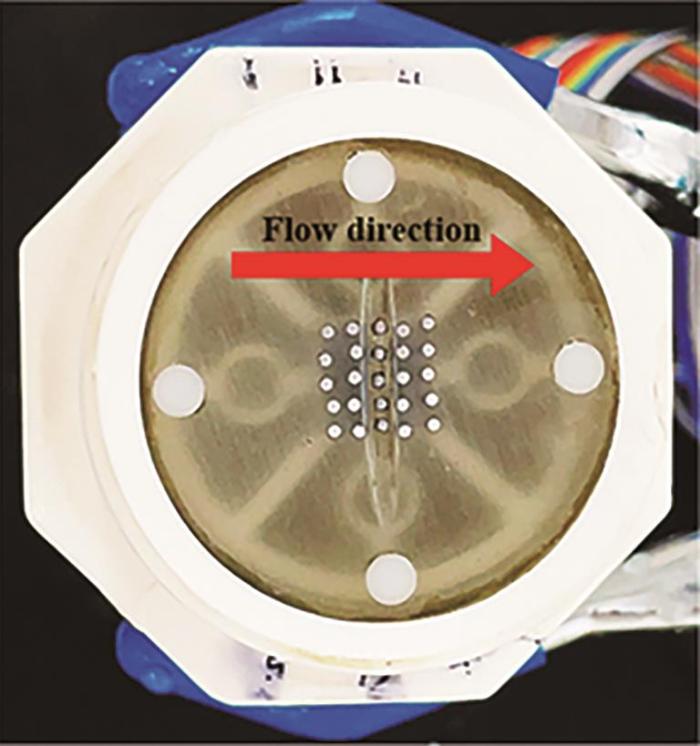
1.1 丝束电极阵列的制备
图1
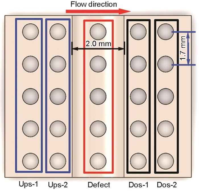
图2
将封装完毕的丝束电极装入循环流动腐蚀测试环路中。腐蚀测试环路中的测试通道长度为600 mm,宽度为10 mm,高度为4.5 mm。循环流动腐蚀测试环路示意图如图3所示。测试溶液选用CO2饱和的NACE溶液来充分模拟实际管道中存在的输运凝析液,NACE溶液质量配比为:H2O∶NaCl∶HAC=945 g∶50 g∶5 g,流体冲刷流速设定为3 m/s。
图3
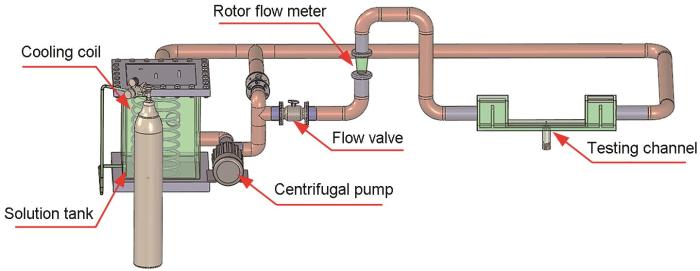
图3
循环流动腐蚀测试环路示意图
Fig.3
Schematic diagram of a single-channel circulating flow accelerated corrosion test loop
1.2 WBE测试
将预先封装的三电极体系装入单通道循环流动加速腐蚀测试环路进行局部腐蚀电流及电位的测试。待测试样所处环境为CO2饱和的NACE溶液中,温度为 36℃,pH为2.72,冲刷时间为12 h。
WBE测试是基于Labview测试环境开发的电偶电流及电位的腐蚀测试系统。WBE自动测量系统的硬件设施包括数字式万用表(PXI-4071)、快速矩阵转换开关模块(PXI-2535)、有效的电流保护放大器(PXI-4022)。数字万用表其电压测量范围为10 nV~1000 V,输入电阻大于1010 Ω。在进行电偶电流和电位的测试前,将电极丝全部耦接直至获得稳定的开路电位(OCP)。达到稳定开路电位之后将25根电极丝按照既定顺序连接PXI-4071和PXI-2535,结合Labview开发的快速矩阵转换开关模块记录每根电极丝的电偶电流及电位。25根微电极的局部腐蚀电位是基于参比电极-纯锌进行测量。在测量电偶电流时,电偶对必须处于短路状态。将25根电极丝按照既定顺序连接PXI-4071和PXI-4022,以便将每个电极丝与电极阵列分开,然后获得该电极丝与电极阵列之间的电偶电流。依次连接剩余所有电极丝端口进行电偶电流测试。整个测量过程(局部电偶电流和电位)由在NI™ LabVIEW™环境中开发的虚拟设备程序控制。
1.3 EIS 测试
为了更加充分理解缺陷区的电化学腐蚀行为,在进行WBE测试的同时将凹坑缺陷中排布的5根丝耦接一起进行宏观电化学中的电化学阻抗谱测试(EIS),参比电极选用纯锌,对电极为Pt片,通过电荷转移电阻来宏观表征缺陷区的腐蚀特征及电化学反应动力学过程。EIS测试采用Solartron 1287+1255B电化学测试系统,为了避免实验室工频信号的干扰,测试过程中扫描频率为99 kHz~0.01 Hz,以振幅为5 mV的正弦交流信号对电化学阻抗谱测试过程进行外加干扰。
1.4 流体动力学模拟
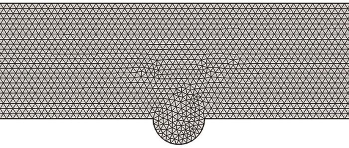
采用基于雷诺数平均Navier-Stokes方程中的K-ε湍流模型来研究流体流经缺陷区的连续流动状态变化。利用COMSOL建立与缺陷尺寸相对应二维模型,二维模型的长度设置为600 mm,宽度设置为4.5 mm,以保证测试通道的尺寸;缺陷宽度设置为2 mm,深度为1 mm。在网格划分过程中,为了向缺陷区的平稳过渡,网格划分的最大迭代次数设置为8次,边界层最大单元深度为16次,缺陷区网格划分二维模型如图4所示。流体的速度设置为3 m/s。同时,为保证充分发展的自由流动,出口压力设置为101325 Pa。
图4
2 实验结果
2.1 WBE测试结果
图5为缺陷试样在流体冲刷不同时刻的电偶电流分布。橙红色区域代表阳极区,电流密度为正值;深蓝色区域代表阴极区,电流密度为负值。沿着流动方向将试样按排列分布依次设定为上缘第1排(上1)、上缘第2排(上2)、中间第3排缺陷底层区(缺陷)、下缘第1排(下1)、下缘第2排(下2),并用中间红色框线框出。从电偶电流不同时刻分布图中可以发现,在流动冲刷腐蚀的最初第1 h内,缺陷区存在较正的电流密度,表现为阳极,紧邻缺陷两侧电极丝均表现为阴极。随着流动冲刷的进行,缺陷区阳极电流密度逐渐消失,发生极性偏转,缺陷区呈现阴极电流密度。当流动冲刷腐蚀时间持续到4~6 h时,缺陷区表现出较明显的阴极区,缺陷下缘第一排(下1)逐渐表现出较明显的阳极区。随着腐蚀的继续进行,阴极区与阳极区不再发生变化,但阴极电流密度以及阳极电流密度均逐渐增加。在3 m/s流速冲击下,凹陷区会聚集大量腐蚀性介质,由于几何形状影响,大量腐蚀性介质将潜藏于此,诱发凹陷区电极丝发生阳极溶解;当Fe2+与CO32-的浓度达到Ksp时,会发生腐蚀产物膜的堆积,进而凹陷区的腐蚀被抑制[17, 18]。
图5
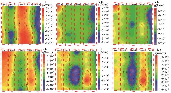
图5
微电极阵列测试下电偶电流等值线分布图
Fig.5
Distribution of galvanic current contours during the microelectrode array test
由图5可以看出,微电极各排电极丝随着时间的变化呈现出明显的规律性。因此,利用
式中,i为各分区电偶电流。
阵列电极在流体冲刷状态下不同排列之间的平均电偶电流分布见图6。可以发现,流体流经缺陷处时由于流动状态的改变将导致溶液中腐蚀介质向基体中的传递过程发生改变,进而导致缺陷区(第3排)及其周边区域(第2排及第4排)存在电化学分布的不均匀性。缺陷区(第3排)具有绝对值较大的阴极电流密度而表现为阴极,腐蚀进行缓慢。紧邻缺陷两侧的上下游区域(第2排及第4排)由于承受较大湍流动能的影响,会较容易发生溶解而作为阳极,具有较大的阳极电流密度,该区域腐蚀更严重。随着冲刷腐蚀时间的延长,作为阴极腐蚀电流密度及阳极腐蚀电流密度均呈现逐渐增加的趋势,表明阴、阳极腐蚀加剧。此外,缺陷区(第3排)长时间作为阴极将通过混合电势理论增加阴阳极区的电偶电流差异,产生阳极极化促进阳极腐蚀加剧[18]。
图6

图6
WBE测试下各分区平均电偶电流的分布变化图
Fig.6
Distribution of average galvanic currents during WBE testing.
2.2 缺陷试样不同分区的EIS变化
通过微电极阵列测试所得亚微观尺度电偶电流分布差异可以看出,由于各分区电偶电流大小各异导致缺陷不同区域腐蚀存在较大腐蚀差异性。为了更清晰地了解缺陷各分区在微湍流影响下的腐蚀过程动力学特征,采用电化学阻抗谱测试技术(EIS)将凹坑缺陷及缺陷上下游中排布的5根丝耦接一起进行电化学阻抗谱测试,通过电荷转移电阻来宏观表征缺陷各分区的腐蚀差异及电极过程动力学过程。图7展示了缺陷试样不同分区冲刷12 h之后不同排数之间所呈现Nyquist谱图响应与Bode图变化曲线。冲刷结束之后的Nyquist图在上1、上2、缺陷、下2排列的耦合中均呈现双容抗弧特征,高频段小的半圆弧和中低频段一个较大的半圆弧;仅仅在下1排列的耦合中体现单一半圆弧特性。高频段的小半圆弧表示冲刷结束后表面腐蚀产物膜的形成,中低频段半圆弧表示电极与溶液界面之间的双电层体系,半圆弧半径的大小表征溶液中电荷转移所遇到的阻力。
图7

图7
试样不同位置在冲刷12 h之后的EIS谱图变化
Fig.7
Nyquist and Bode plots of EIS of the different zones of the sample after 12 h erosion corrosion
图8
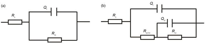
图8
用于EIS拟合的等效电路模型
Fig.8
Equivalent circuit models used for EIS fitting. (a) lower 1; (b) upper 1, upper 2, defect, lower 2
表1 缺陷试样不同排列耦合的阻值参数变化
Table 1
| Position | Rs/Ω·cm2 | Y0(Qf)/Ω-1 cm-2s n | Rf/Ω·cm2 | Y0(Qct)/Ω-1 cm-2s n | Rct/Ω·cm2 |
|---|---|---|---|---|---|
| Upper 1 | 6.670×10⁻¹ | 6.475×10⁻⁴ | 3.309 | 5.762×10⁻³ | 14.41 |
| Upper 2 | 5.281×10⁻¹ | 4.645×10⁻³ | 3.003 | 6.359×10⁻³ | 10.08 |
| Defects | 6.973×10⁻¹ | 5.264×10⁻³ | 3.682 | 3.169×10⁻³ | 15.27 |
| Lower 1 | 5.608×10⁻¹ | - | - | 2.344×10⁻² | 5.092 |
| Lower 2 | 6.523×10⁻¹ | 9.729×10⁻⁴ | 3.133 | 6.353×10⁻³ | 14.58 |
结合图7以及表1可以发现,缺陷区(第3排)电极丝排列耦合整体的低频段容抗弧半径弧最大,缺陷区(第3排)的电荷转移电阻最大,表明缺陷区(第3排)腐蚀进行的最为缓慢。上缘第一排(上1)和下缘第二排(下2)呈现相似的低频段半圆弧大小且电荷转移电阻阻值相近;表明上1和下2位置存在的相似的电化学腐蚀动力学过程且两区域的腐蚀差异不大。下缘第一排(下1)及上缘第二排(上2)位置的电荷转移电阻介于下缘第一排(下1)和上缘第一排(上1)之间,且下缘第一排(下1)电极丝耦合整体具有最小的电荷转移电阻,表明下1位置所承受的电荷转移阻力较小,下1位置腐蚀更为严重电极丝耦合整体相比于缺陷区域呈现较小的阻力,也较容易遭受腐蚀。这与通过WBE测试的局部电偶电流分布所得结论一致。
2.3 腐蚀形貌变化
沿着流动方向选取中间一行电极丝进行腐蚀产物形貌分析,其形貌变化如图9所示。从腐蚀产物形貌变化可以看出,在缺陷底层区域均形成致密的腐蚀产物膜,导致边界层厚度增加,致密的腐蚀产物膜将阻滞腐蚀性介质与基体之间的接触,从而引起电荷转移过程受阻。缺陷下缘第二排(下2)和缺陷上缘第一排(上1)也均形成相对致密的腐蚀产物膜,但相比缺陷底层致密性较差,因此呈现出比缺陷底层稍小的电荷转移电阻。缺陷下缘第一排(下1)在局部微湍流的作用下承受较大的湍流动能冲击,腐蚀产物呈现疏松网格状结构,导致基体暴露于腐蚀性溶液中;疏松网格状腐蚀产物膜有助于腐蚀性介质更好地钉扎在基体表面,加速腐蚀进程。因此,缺陷下缘第一排(下1)呈现较小的电荷转移电阻。缺陷上缘第二排(上2)由于回旋涡流的影响,导致此区域可能遭受流体的二次冲击,仍然会形成较为疏松的网格状结构,且仍有部分基体裸露在外侧,但致密度相比下缘第一排略有加强,腐蚀倾向相比远离缺陷区域(下缘第二排(下2)和上缘第一排(上1))仍较为严重。
图9

图9
中间一行电极丝腐蚀形貌
Fig.9
Corrosion morphologies of the electrode wires in the middle row.
图10

图10
去除腐蚀产物膜之后的三维形貌和缺陷区去除腐蚀产物前后的深度变化
Fig.10
(a) 3D morphology of the pit defect after removing corrosion product film, (b) depth changes after removing the corrosion products on the pit defect
2.4 CFD模拟
通过COMSOL中的流体力学模块对凹陷及其周围区域的流动状态进行仿真模拟,分析缺陷不同位置处的速度、湍流动能、壁面剪切力及湍流耗散率的分布变化。为了更好地理解缺陷不同分区的流体动力学参数变化,结合图11所示的缺陷不同分区示意图,沿流动方向将依次定义为:a)缺陷上缘区,b)缺陷内部上游区,c)缺陷内部底层区,d)缺陷内部下游区,e)缺陷下缘区。
图11
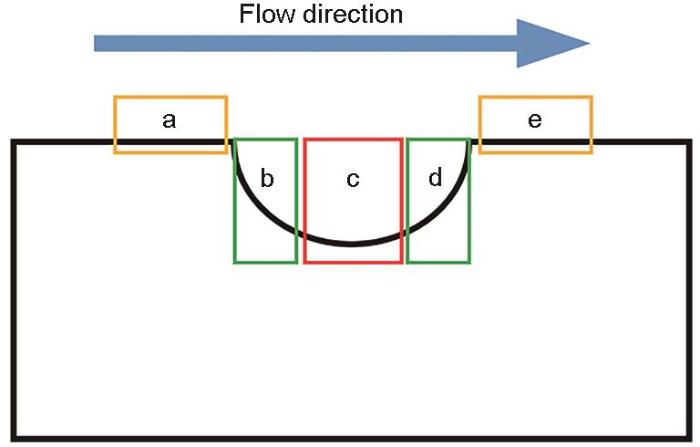
图12
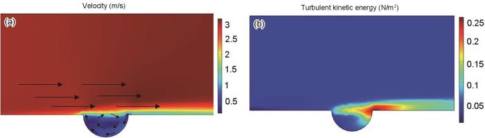
图12
缺陷及其周边区域的流速及湍流动能分布变化
Fig.12
The flow velocity and turbulent energy distribution changes in the defect and its surrounding area
图13展示了缺陷区近壁面的壁面剪切应力分布变化。由于溶液介质本身粘性的存在,且沿竖直方向存在速度梯度,导致管壁形成流体边界层,壁面剪切应力是边界层流动状态的一个重要物理参数。壁面剪切应力与壁面摩擦阻力耦合表示为:
其中,
图13
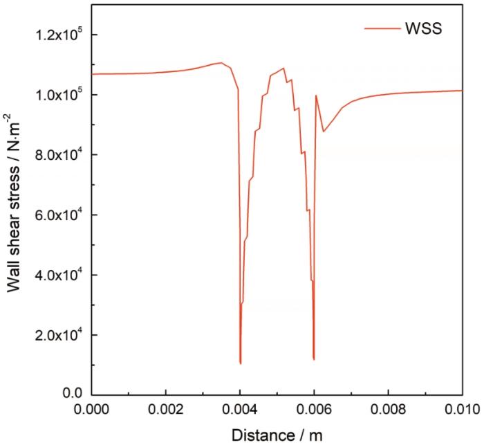
图13
缺陷及其周边区域壁面剪切力变化曲线
Fig.13
The change curve of wall shear stress in the defect and its surrounding area.
图14展示了缺陷区近壁面湍流动能耗散率的分布变化。流动能耗散率是指在分子粘性作用下由湍流动能转化为流体内能的速率,湍流动能耗散率越大,则该区域流体内能较大,流体热运动较为剧烈,离子热运动也相对更频繁,加速该区域腐蚀性介质的扩散传质进程。从图中可以看出,沿着流动方向在缺陷上缘区首先出现一个湍流耗散率峰值,湍流耗散率在此处最大值约为104 m2/s3,当流体流经凹陷内部时随即下降,到达缺陷下缘区时出现一个新的湍流耗散率峰,此处湍流耗散率最大值为624 m2/s3;当流体远离凹陷下缘区时,湍流耗散率随即下降,但其值仍大于凹陷上缘区及凹陷内部的湍流耗散率大小。凹陷下缘区由于较高的湍流耗散率而使得该区域流体具有较大内能,导致该区域腐蚀性介质扩散传质进程发展较快。
图14
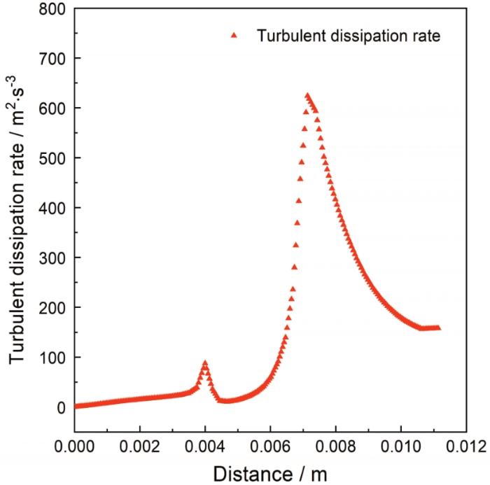
图14
缺陷区湍流耗散率变化曲线
Fig.14
The change curve of turbulent dissipation rate in the defect area.
3 分析讨论
3.1 CO2 腐蚀中的电化学反应机理
由于缺陷自身几何形态的影响,导致流体流经缺陷区随即发生扰动,湍流动能发生较大变化。由图9可以看出,缺陷下缘拐角处即缺陷下缘第一排(下1)区域存在较大的湍流动能,长期存在较大的壁面剪切应力,不利于致密腐蚀产物膜的形成。因此,下游第一排电极丝(下1)的电荷转移电阻较小,腐蚀最严重。此外,缺陷区域对高涡流度引起的高质量H+传质产生了高势能。这些高电势驱使一些“电流”从低电势的区域向高的涡流度区域流动,缺陷下缘承受高湍流度区域聚集大量H+,导致缺陷下缘第一排电极丝(下1)存在较大的腐蚀电流密度[26]。大量H+聚集将缓冲和解离阴极反应,H+ 成为电化学腐蚀反应进行快慢的决定性因素,流动冲刷体系下电化学腐蚀过程的电荷转移是通过阴极反应还原氢离子来实现的,电化学腐蚀反应中H+的极限电流密度可表示为:
式中,
式中,
3.2 流体传质过程分析
式中,K是校正因子,v是总传质速率,
壁面剪切应力是边界层流动状态的一个重要物理参数,对流体边界层的厚度产生较大影响。
式中,
4 结论
(1) 在流动冲刷状态下,管道缺陷区域在CO2饱和的NACE溶液中存在较大的腐蚀差异性。
(2) 缺陷底层以及远离缺陷区域受局部湍流影响较小,存在较大的阴极电流密度以及较大的电荷转移电阻,表现为阴极;紧邻缺陷两侧的上下缘区域受局部湍流作用较大,具有较大的阳极电流密度及低的电荷转移电阻,表现为阳极,缺陷上下缘区腐蚀较严重。
(3) 缺陷上下缘区的阳极电流密度以及缺陷底层区的阴极电流密度均随时间的延长而逐渐增大,表明凹陷整体呈现腐蚀加剧的倾向。
(4) 缺陷区局部湍流导致缺陷内部下游区和紧邻缺陷的下缘区遭受较大的壁面剪切应力以及湍流耗散率的影响,离子扩散传质作用增强,腐蚀加剧。随着流动冲刷腐蚀的持续进行,缺陷区有向缺陷两侧的上下缘区域逐渐和扩展的趋势。
参考文献
Analysis of corrosion factors and discussion of protection countermeasures of long-distance buried oil and gas pipeline
[J].
长输地埋油气管道腐蚀因素分析与防护对策探讨
[J].
Development mechanism of internal local corrosion of X80 pipeline steel
[J].
In situ SECM observation of corrosion behavior of carbon steel at defects of epoxy coating under AC current conditions
[J].
扫描电化学显微镜原位观察碳钢涂层缺陷处的交流腐蚀行为
[J].
将原位微区电化学与传统宏观电化学技术相结合,应用电化学扫描显微镜(SECM)技术和电化学阻抗谱技术并结合微观形貌分析,研究了碳钢涂层缺陷处在不同交流电流强度下的腐蚀行为。结果表明:SECM拓扑形貌直观反映了碳钢涂层缺陷处局部腐蚀过程中电化学活性点的变化。交流电流使涂层缺陷处腐蚀活性点的数量明显增多,且使表面腐蚀产物积累对腐蚀产生的抑制作用明显减弱;浸泡初期涂层缺陷处的腐蚀为电子转移控制过程,浸泡10 h后转为扩散控制过程;随着交流电流强度的增大和浸泡时间的延长涂层的剥离程度提高,点蚀坑的深度和宽度随之增大。
CO2 corrosion control in steel pipelines. Influence of turbulent flow on the performance of corrosion inhibitors
[J].
Research of residual strength evaluation methods of the high-strength steel gas pipeline with internal corrosion defects
[D].
含内腐蚀缺陷高强钢输气管道剩余强度的评估方法研究
[D].
Empirical equation of CO2 corrosion with presence of low concentrations of acetic acid under turbulent flow conditions
[J].
Key issues related to modelling of internal corrosion of oil and gas pipelines – A review
[J].
Effect of AC on stress corrosion cracking behavior and mechanism of X80 pipeline steel in carbonate/bicarbonate solution
[J].
The role of surface film on the critical flow velocity for erosion-corrosion of pure titanium
[J].One of the key issues in clarifying the mechanism of critical flow velocity (CFV) for erosion-corrosion is whether the surface film is ruptured mechanically below the CFV. This paper aims to address such an issue for titanium by using ion-labelling and colour-labelling methods. The results show that the pre-labelled ion and colour cannot be detected on the titanium surface after impingement in liquid-solid two-phase fluid below the CFV, suggesting the surface film has been ruptured mechanically. Accordingly, the phenomenon of CFV is attributed to the competition between the depassivation process induced by solid particle impacting and the subsequent repassivation process. Furthermore, a critical criterion is proposed and the expressions of depassivation time and repassivation time are derived and discussed.
Development mechanism of local corrosion pit in X80 pipeline steel under flow conditions
[J].
Experimental and numerical studies on mass transfer characteristics behind an orifice in a circular pipe for application to pipe-wall thinning
[J].
Modeling of mechano-electrochemical interaction between circumferentially aligned corrosion defects on pipeline under axial tensile stresses
[J].
Ultimate strength assessment of plated steel structures with random pitting corrosion damage
[J].
Study of localized corrosion of 304 stainless steel under chloride solution droplets using the wire beam electrode
[J].
Wire beam electrode technique for investigating galvanic corrosion behavior of hot-dip galvanized steel-scratch defect
[J].
热镀锌钢材的电偶腐蚀行为-划痕型缺陷
[J].使用锌--碳钢异材质丝束电极技术, 模拟并研究了锌/钢电偶腐蚀不同阶段的电位和电流密度的空间分布. 结果表明, 在锌丝与钢丝面积比为10 : 1的情况下, 锌丝能给钢丝提供足够的阴极保护, 且锌丝之间存在明显的电位、电流分布不均现象; 钢丝之间也存在电化学参数分布不均现象, 而且在受到保护的同时钢丝表面有氢析出.
Influence of temperature on corrosion rate and porosity of corrosion products of carbon steel in anoxic bentonite environment
[J].
On the localised corrosion of carbon steel induced by the in-situ local damage of porous corrosion products
[J].The effect of in-situ local damage of uniform porous corrosion products on the localised corrosion of carbon steel is investigated using the wire beam electrode technique (WBE) combined with morphology characterisation and electrochemical tests. The WBE measurements demonstrate that the localised corrosion is enhanced by the in-situ local removal of porous corrosion products, supported by the morphology characterisation and electrochemical tests. The enhanced localised corrosion does not originate from the damaged wire in WBE where the corrosion products are removed but from the other undamaged wires, which is reported for the first time. A mechanism is proposed that the intensive anodic polarisation effect of the damaged wire on the undamaged wires could account for the enhanced localised corrosion, which is due to the protective corrosion products newly formed on the damaged surface and the increase in the potential of damaged wire.
Evolution of dissolution processes at the interface of carbon steel corroding in a CO2 environment studied by EIS
[J].
Effect of near-wall hydrodynamic parameters on flow induced corrosion
[J].
近壁处流体力学参数对流动腐蚀的影响
[J].
Study on interaction mechanism of local turbulent flow induced by local corrosion of X80 pipeline steel in high shear flow field
[J].
高剪切力流场下X80管线钢局部腐蚀深坑诱导局部湍流交互机理研究
[J].
An experimental and numerical investigation of CO2 corrosion in a rapid expansion pipe geometry
[J].
Effect of pH on the corrosion and electrochemical behavior of 3Cr steel in CO2 saturated NaCl solution
[J].
3Cr低合金钢在含饱和CO2的NaCl溶液中的腐蚀电化学行为
[J].研究了含饱和CO2的NaCl溶液pH值对3Cr低合金钢腐蚀及其电化学行为的影响。结果表明: 当NaCl溶液的pH值较低(2, 3.9)时, 腐蚀产物膜为单层结构, 呈龟裂状; 当pH值较高(6.5)时, 腐蚀产物具有三层结构, 外层腐蚀产物为颗粒状, 内层仍呈龟裂状。NaCl溶液的pH值对3Cr低合金钢的腐蚀电化学行为也有显著影响。 NaCl溶液的pH值升高能改变电极过程中的主要阴极反应, 使腐蚀电位逐渐负移, 且电荷转移电阻的增大使腐蚀电流密度减小。
A review of iron carbonate (FeCO3) formation in the oil and gas industry
[J].
A mechanistic model for carbon dioxide corrosion of mild steel in the presence of protective iron carbonate films—part 1: theory and verification
[J].
Effect of acetic acid on CO2 corrosion of carbon steel in vapor-water two-phase horizontal flow
[J].
H2S corrosion of mild steel: a quantitative analysis of the mechanism of the cathodic reaction
[J].In the context of H2S corrosion of mild steel, the direct electrochemical reduction of H2S is currently believed to be the main contribution of this species to cathodic currents. That is perhaps due to the distinct behavior of the cathodic polarization curves observed in the presence of H2S, as compared to those obtained in strong acids solutions or in the presence of other weak acids such as carboxylic acids and carbonic acid. In the presence of aqueous H2S, the cathodic polarization curves show a "double wave" shape, that is widely considered to be the result of the direct reduction of H2S. In the present study, the mechanism of H2S corrosion of mild steel is theoretically investigated with the focus on the buffering ability of H2S. It is shown that all characteristic behaviors of cathodic currents that were previously associated with the direct reduction of H2S, including the "double wave", can be fully explained in terms of the H2S dissociation reaction and its buffering effect. In order to further evaluate this mechanistic argument, a comprehensive mathematical model for the H2S system was developed and the calculated cathodic polarization curves were compared with the existing experimental data in the open literature. The results showed that the model, built with H+ reduction as the sole cathodic reaction, is able to reasonably capture all characteristic behavior of cathodic currents, further supporting this mechanistic argument. (C) 2018 Elsevier Ltd.
CO2 corrosion resistance of carbon steel in relation with microstructure changes
[J].
Effects of multiphase flow on internal CO2 corrosion of mild steel pipelines
[J].
Assessment of the effects of acetic acid and turbulent flow conditions on the corrosion of API 5L X52 steel in aqueous CO2 solutions
[J].
Numerical analysis of separation performance of an axial-flow cyclone for supercritical CO2-water separation in CO2 plume geothermal systems
[J].
Electrochemical corrosion behavior of X70 pipeline steel in turbulence zone under jet impingement at high temperature and high pressure CO2 environment
[J].
高温高压喷射湍流区中X70管线钢CO2腐蚀电化学特征
[J].
