


但是,用冷喷涂工艺制备的涂层中颗粒大小不均匀,使涂层中产生微孔隙[10]。涂层中的孔隙有两种类型。第一种类型,颗粒撞击表面时变形不足,颗粒不能完全填充撞击表面的凹凸成为孔隙。产生第二种类型孔隙的原因是,颗粒在涂层线斜坡上的撞击角度不利[11,12]。这两种类型的孔隙在涂层中引入了空隙或空气间隙,影响涂层的机械性能。Zahiri等[13]研究了用冷喷涂技术在纯Ti材料表面沉积的涂层的硬度与孔隙率的关系。孔隙率为0.5%的涂层,其显微硬度达到了300HV,孔隙率为13.5%时硬度降低到100HV。Binder等[14]研究发现,随着孔隙率的提高涂层的抗拉强度降低。Khun等[15]用冷喷涂技术制备的Ti-6Al-4V涂层,其磨损速率随着孔隙率的提高而提高。以上结果表明,孔隙对涂层的性能有重要的影响。
目前,用有限元模拟研究冷喷涂主要侧重于分析在沉积过程中颗粒对基板的冲击行为,包括颗粒和基材的变形以及冷喷涂工艺参数对涂层性能的影响[16~20]。对在摩擦工况下不同形状孔隙裂纹的萌生与扩展规律的研究较少。同时,用有限元模拟分析复合涂层时通常假设颗粒为圆形或者椭圆形,忽略了实际颗粒的不规则性,不利于了解在摩擦工况下孔隙形状对涂层性能的影响。鉴于此,本文采用冷喷涂方法在AZ31镁合金表面制备含30%Al2O3的Al基复合涂层,观测涂层孔隙的大小和形状,研究往复摩擦过程中涂层孔隙处裂纹的萌生和扩展规律,并使用有限元仿真软件建立椭圆形、三角形、矩形和无孔隙复合涂层的模型,分析摩擦过程中涂层孔隙处最大Mises应力和摩擦后最表层残余应力,讨论复合涂层有限元应力结果和往复摩擦裂纹大小之间的关系。
1 实验方法
1.1 实验用原料
实验用基体是用熔铸法制备的AZ31镁合金,其化学成分列于表1。
表1 AZ31镁合金的化学成分
Table 1
| Elements | Al | Zn | Mg |
|---|---|---|---|
| Content | 3 | 1 | Bal. |
图1
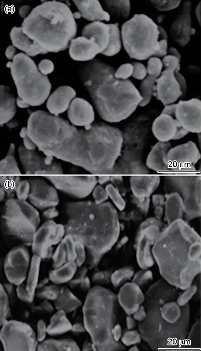
图1
纯Al和Al2O3粉末的SEM形貌
Fig.1
SEM morphology of Al powder (a) and Al2O3 powder (b)
图2

图2
纯Al和Al2O3粉末的粒度分布
Fig.2
Particle size distribution of pure Al and Al2O3 powder
1.2 Al基复合涂层的制备
表2 冷喷涂工艺参数
Table 2
| Spray pressure / MPa | Gas temperature / oC | Powder feeding voltage / mV | Powder feeding rate / g·min-1 | Nozzle distance / mm |
|---|---|---|---|---|
| 1.6 | 230 | 28 | 30 | 30 |
图3
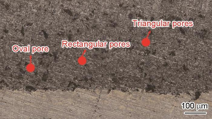
涂层中不同形状的孔隙,椭圆形、三角形和矩形孔隙的概率大致相同(图4)。孔隙的平均面积为7.96 × 10⁻⁵ mm2,椭圆形孔隙平均长轴长度为20 μm,三角形孔隙平均底长为10 μm,矩形孔隙平均长度为15 μm。涂层没有出现裂纹。
图4
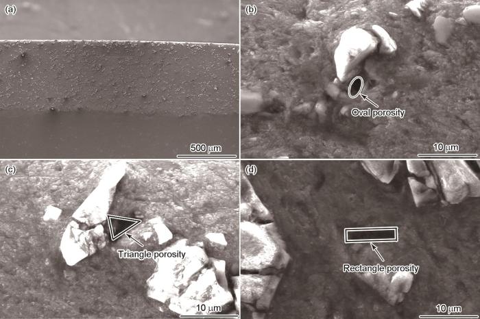
图4
涂层和不同形状孔隙的电镜照片
Fig.4
Electron micrographs of coatings and pores of different shapes (a) coating; (b) elliptical pores; (c) triangular pores; (d) rectangular pores
1.3 测试摩擦磨损性能
用布鲁克TriboLab摩擦磨损实验机测试涂层的摩擦磨损性能,对磨副Si3N4陶瓷球的直径为4 mm、表面粗糙度为Ra = 0.018 μm。施加的载荷为10 N,往复行程为40 mm,频率为0.5 Hz,实验时长为20 min。
用线切割切取往复摩擦后涂层的横截面试样,以观察涂层裂纹的扩展。因为涂层的磨损较小,只考虑摩擦对涂层孔隙的影响。
2 构建有限元模型
使用Abaqus有限元软件和Python语言脚本并考虑到二维有限元分析,建立了孔隙率为1.91%且不同形状孔隙以及无孔隙的Al基复合涂层二维模型[21]。模型基体的尺寸为0.5 mm × 0.3 mm,冷喷涂涂层的尺寸为0.5 mm × 0.1 mm,涂层中Al2O3颗粒的粒径为25 μm。图5给出了无孔复合涂层和有不同形状孔隙涂层的模型。孔隙和不规则多边形Al2O3颗粒随机分布在涂层内。鉴于实际冷喷涂涂层中纯Al和Al2O3颗粒之间以及涂层与基体之间的结合强度非常高,因此假设它们之间的结合是完美的[22,23]。虽然实际的冷喷涂复合涂层中Al2O3的沉积效率未达30%,为了研究涂层内部的应力传递和应力集中,将Al2O3含量设置为30%。为了直观的体现孔隙对涂层的影响,本文参考文献[24]的结果将涂层中每种孔隙设置为相同形状且大小相等。从图4可见,孔隙的形状为近似椭圆形、三角形、矩形。参考文献对孔隙形状的描述和非标准孔隙形状在有限元分析中引起数值误差或奇异性,进行标准化以降低出现这些问题的可能性和使分析更加稳定[25~27]。因此,将涂层中孔隙的形状设置为标准的椭圆形、三角形和矩形。三种孔隙随机分布在涂层中,为了更好体现不同孔隙对涂层的影响,每种孔隙相对涂层的位置不变。
图5
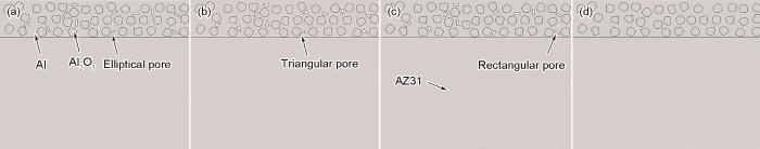
图5
复合涂层中不同形状孔隙的模型
Fig.5
Composite coating models with different pore shapes (a) elliptical pores; (b) triangular pores; (c) rectangular pores; (d) no pores
涂层网格单元的尺寸为0.002 mm,网格由四边形单元(CPE4R)和少量的三角形单元(CPE3)组成。采用单精度划分镁合金两侧的网格,最小尺寸为0.003 mm,最大尺寸为0.005 mm,全部采用CPE4R单元。网格划分结果如图6所示。采用显示动力学模块,分析摩擦工况。刚体与涂层表面的相互作用,设定为表面与表面接触,法向接触为硬接触,切向接触为罚接触并设摩擦系数为实验测出的数值。为了准确捕捉材料可能发生的非线性行为,材料属性模块中的纯Al颗粒和AZ31镁合金基体选用J-C本构模型,而Al2O3陶瓷采用JH-2本构模型。本文重点分析应力分布及其数值以预测裂纹行,故不需考虑本构的损伤参数[28~33]。
图6

图6
复合涂层中不同形状孔隙的模型网格
Fig.6
Model meshes of composite coatings with different pore shapes (a) elliptical pores; (b) triangular pores; (c) rectangular pores; (d) no pores
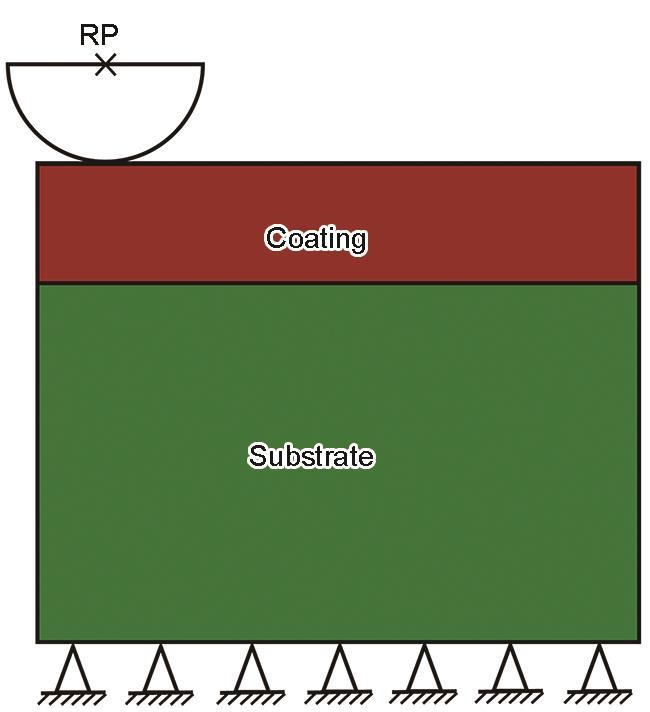
摩擦示意图如图7所示,压头建模为解析刚体。采用两步骤分析模型。第一步,是在参考点施加10 N线性力并使刚体以200 mm/s速度进行摩擦;第二步,是卸载过程即将刚体向上移动。
图7
3 结果和讨论
3.1 有限元模拟结果
有限元模拟分析,用Mises应力(也称等效应力或者von Mises应力)评估材料的强度和破坏行为。图8给出了不同形状孔隙在摩擦过程中的Mises应力云图。可以看出,在三种形状的孔隙(椭圆形、三角形、矩形)周围发生了较为明显的应力集中。椭圆形孔隙应力集中在其长轴端点区域,矩形和三角形孔隙集中在尖角处。图中的空隙代表涂层中的孔隙,载荷不能均匀分布在其表面,使其成为应力集中点而产生应力集中。椭圆形孔隙长轴端点位置的曲率半径较小,导致应力集中。矩形和三角形多边形结构的孔隙,其尖角处的几何不连续性导致应力场强度急剧提高,传播至尖角处的外部载荷无法平滑地分散到此区域,导致应力集中。
图8
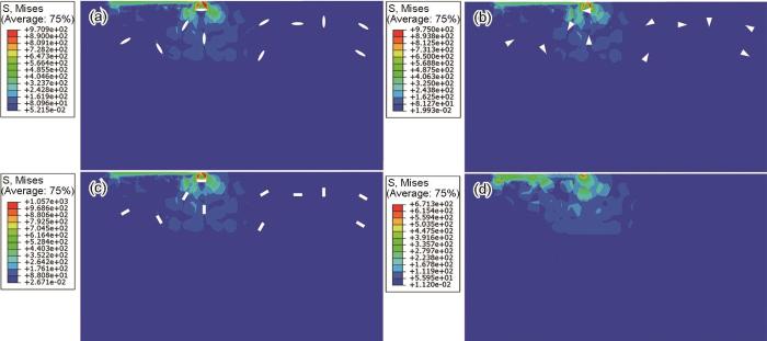
图8
冷喷涂涂层摩擦Mises应力云图
Fig.8
Frictional Mises stress cloud diagram of cold spray coating (a) elliptical pores; (b) triangular pores; (c) rectangular pores; (d) no pores
从图8d可以看出,无孔隙涂层的应力分布比有孔隙(椭圆形、三角形、矩形)涂层均匀且应力集中区域更少。由于载荷无法均匀分布在孔隙表面,阻碍了应力的传递。与无孔隙涂层相比,有孔隙涂层容易中断应力传递,使周围区域产生较高的应力。表3列出了在摩擦过程中不同形状孔隙处Mises应力最大值,可见在摩擦过程中涂层内椭圆形、三角形和矩形孔隙的最大Mises应力值依次增大。与矩形和三角形孔隙相比,椭圆形孔隙的几何形态连续且光滑,有利于缓解应力集中,使应力分布更加均匀,减小了Mises应力值。与三角形孔隙相比,四个角锐利的矩形孔隙在应力作用下产生更多的高应力集中区域,其Mises应力值更大。由表3可以看出,三种孔隙处最大Mises应力值已经超过纯铝的屈服强度(172 MPa),使孔隙发生塑性变形并可能导致裂纹的生成[34]。
表3 不同形状孔隙在摩擦过程中的最大Mises应力
Table 3
| Pore shape | Oval | Triangle | Rectangle |
|---|---|---|---|
| Mises stress maximum value / MPa | 832.03 | 883.35 | 920.29 |
| Increased Mises maximum value compared to non-porous coating | 19.32% | 24.00% | 27.05% |
残余应力是材料受到的外力留存的部分。冷喷涂涂层中会产生残余应力,为了简化模型本文不考虑冷喷涂实验产生的残余应力,只考虑摩擦产生的残余应力[35]。图9给出了不同形状孔隙摩擦后S11(图9a~d)、S22(图9e~h)应力分布云图,其中S11、S22分别为模型中与x轴和y轴平行的应力分量。从图9可以看出,摩擦后的涂层S11最表层单元网格均为拉应力,涂层S11应力从表面到界面拉应力转变为压应力再转变为拉应力。在摩擦过程中涂层的表层经历了较大的塑性变形,金属材料还发生一定程度的回弹。次表层因未发生相同程度的变形而制约了最表层的回弹,使最表层产生残余拉应力,次表层则产生残余压应力[36]。根据石等[37]的结果,摩擦后最表层平均残余拉应力反映出涂层内孔隙裂纹长度和宽度。平均残余拉应力越大,表明涂层内裂纹的长度和宽度越大。图10给出了不同形状孔隙摩擦后最表层单元S11和S22应力平均值。可以看出,无孔隙的涂层最表层S11、S22拉应力小于有孔隙的涂层最表层的拉应力。涂层中的孔隙和Al2O3影响内应力的分布和再分布。涂层受到外力作用时,应力在涂层结构内转移和重新分布。与无孔隙涂层相比,有孔隙的涂层更容易中断应力传递,在孔隙周围产生更高的应力。在无孔涂层中只有Al2O3中断应力的传递,应力分布比含有孔隙的涂层更均匀,使表层的残余应力值较低[38]。与三角形和椭圆形孔隙涂层相比,矩形孔隙涂层的S11和S22残余应力平均值最高。从表3可以看出,矩形孔隙的Mises应力值最大,更容易产生断裂点,使其断裂点密度较高和表面残余应力最大[39]。
图9

图9
冷喷涂涂层的摩擦S11、S22应力云图
Fig.9
Friction S11 and S22 stress cloud diagrams of cold sprayed coatings (a, e) elliptical pores; (b, f) triangular pores; (c, g) rectangular pores; (d, h) no pores
图10

图10
不同形状孔隙摩擦最表层S11和S22应力的平均值
Fig.10
Average stress of the surface elements S11 and S22 for pores with different shapes in process of friction
3.2 往复摩擦后孔隙中的裂纹
冷喷涂涂层比其他涂覆的涂层致密,孔隙的尺寸较小,且因其硬度大摩擦后孔隙形状与摩擦前相同[40]。图11给出了往复摩擦后横截面孔隙处的电镜照片。从图11可见,椭圆形孔隙中的裂纹在长轴端点处萌生和扩展。矩形和三角形孔隙的裂纹起源于尖角处,并在此区域扩展。上述区域的尺寸突变或曲率半径最小,导致应力集中。当应力达到一定程度时,裂纹生成并扩展。三种不同形状(椭圆形、三角形和矩形)孔隙的裂纹其长度和宽度不同。图12给出了测出的不同形状(椭圆形、三角形和矩形)孔隙裂纹的长度和宽度。从图12可以看出,椭圆形、三角形和矩形孔隙的裂纹长度和宽度依次增大。其原因是,矩形孔隙的四个尖角导致应力更容易集中,使应力集中区域更多和应力值更大。椭圆形孔隙接近圆形,形状圆滑且尺寸没有明显的突变,产生的应力集中小于矩形和三角形孔隙。
图11
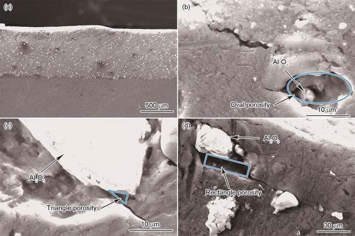
图11
往复摩擦后涂层及不同形状孔隙电镜图
Fig.11
SEM images of coatings and pores of different shapes after reciprocating friction (a) coating; (b) rectangle; (c) triangle; (d) ellipse
3.3 讨论
在冷喷涂涂层中必然出现孔隙,摩擦过程中的摩擦力在涂层内产生应力。孔隙破坏了原本连续的应力分布,导致Mises应力集中和裂纹的萌生和扩展。从摩擦过程中的Mises应力云图(图8)可以看出,与无孔隙涂层相比,含有孔隙的涂层应力分布变得复杂且应力集中显著。有限元模拟结果表明,涂层中椭圆形、三角形、矩形孔隙处Mises应力的最大值分别比无孔隙涂层的最大Mises应力分别高19.32%、24%、27.05% (表3)。位于涂层表面附近的孔隙承受更多的应力,应力集中使这些区域更容易产生裂纹[41,42]。涂层中不同形状的孔隙引起不同类型的应力分布。椭圆形孔隙应力集中主要发生在长轴的端点处,矩形、三角形孔隙的应力集中在尖角处较为显著。而这种应力集中导致局部塑性变形或开裂,从而使材料在较低的应力水平下失效[43]。椭圆形、三角形和矩形孔隙处的Mises应力最大值依次增加(表3)。其原因是,矩形比三角形的尖角更多,其显著的应力集中使Mises应力最大值更大。与矩形、三角形孔隙相比,椭圆形孔隙的轮廓较为圆滑且没有尖锐的尖角,其Mises应力最大值在三种孔隙涂层中最低。
摩擦后产生的残余应力,是摩擦表面的局部塑性变形和应力集中引起的。从摩擦后的S11应力云图及其图例(图9)可以看出,摩擦后涂层最表层的S11残余应力为拉应力,次表层则为压应力,涂层最下层则为拉应力。其原因是,在摩擦过程中涂层的表层发生了塑性形变和弹性形变,次表层以弹性形变为主,摩擦完成后次表层未变形金属的制约使最表层产生残余拉应力而次表层产生残余压应力。而摩擦后最表层的残余拉应力,反映出涂层内孔隙裂纹的长度和宽度。在S11方向上椭圆形孔隙的平均残余应力为97.91 MPa,三角形孔隙为105.56 MPa,而矩形孔隙为107.14 MPa。在S22方向上,相应的平均残余应力值分别为2.30、2.38和2.50 MPa。随着涂层中椭圆形、三角形和矩形孔隙处Mises最大值的增大(表3),三种孔隙涂层内断裂点依次增多,其断裂点密度的提高使最表层平均残余应力依次增大,导致涂层内孔隙处的裂纹长度和宽度增大。
原始孔隙周围并未出现裂纹(图4),实验后出现的裂纹(图11)是在往复摩擦过程中在孔隙周围出现的。从图11可观察到,裂纹在孔隙处向纯Al颗粒中萌生并扩展且并未在Al2O3颗粒中发现裂纹,而Al2O3颗粒的破碎则是在冷喷涂沉积过程中受到高速气流的冲击和撞击所致。裂纹向纯Al颗粒萌生并扩展的原因是,Al2O3颗粒比纯Al颗粒的屈服强度更高,而裂纹的萌生和扩展则影响纯Al和Al2O3颗粒的结合,产生薄弱点进而影响涂层的摩擦性能[44]。在不同形状的孔隙中裂纹萌生和扩展位置不同。椭圆形孔隙的裂纹则从长轴端点处开始萌生和扩展,而矩形和三角形孔隙的裂纹起源于尖角处。上述区域几何特征的特殊性,导致应力线集中和应力集中,应力达到临界值时裂纹开始形成并扩展。根据电镜照片测得椭圆形、三角形和矩形孔隙往复摩擦后横截面孔隙处的裂纹长度平均值分别为4.35、7.37、12.31 μm,宽度平均值分别为0.34、0.39、0.42 μm。
图12
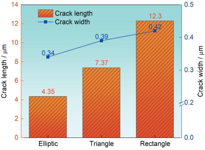
图12
不同形状孔隙中裂纹的长度和宽度
Fig.12
Crack length and width of pores with different shapes
4 结论
(1) 含30%Al2O3的Al基复合涂层中孔隙的形状,主要有椭圆形、三角形和矩形。在摩擦过程中,椭圆形孔隙中的应力集中主要发生在长轴的端点处,三角形和矩形孔隙在其尖角处的应力集中较为显著。在摩擦后,从表层到界面残余应力由拉应力变为压应力再转变为拉应力,涂层中椭圆形、三角形和矩形孔隙的Mises应力最大值及表面平均残余应力依次增大。
(2) 往复摩擦后在孔隙周围出现裂纹,在Al2O3颗粒中没有出现裂纹,孔隙周围的裂纹影响纯Al及Al2O3颗粒的结合能力,进而影响涂层的摩擦性能。椭圆形孔隙中的裂纹从长轴端点处萌生和扩展,而矩形和三角形孔隙的裂纹起源于尖角处。往复摩擦后椭圆形、三角形和矩形孔隙横截面对应的裂纹长度和宽度依次增大。
(3) 有限元分析的结果表明,在摩擦过程中涂层孔隙处Mises最大应力的增大,导致摩擦后最表层平均残余应力增大,从而使裂纹的长度和宽度增大。
参考文献
Magnesium: Industrial and research developments over the last 15 years
[J].
Stress corrosion cracking behavior of micro-arc oxidized AZ31 alloy
[J].
Cold spraying-A materials perspective
[J].
Kinetics of composite coating formation process in cold spray: Modelling and experimental validation
[J].
The effect of pure aluminum cold spray coating on corrosion and corrosion fatigue of magnesium (3%Al-1%Zn) extrusion
[J].
On fatigue behavior of cold spray coating
[J].
Applications of magnesium and its alloys: a review
[J].
Friction stir processing of magnesium alloys: a review
[J].
On the microstructure-dependency of mechanical properties and failure of low-pressure cold-sprayed tungsten carbide-nickel metal matrix composite coatings
[J].
Cold spray additive manufacturing and repair: Fundamentals and applications
[J].
Cold spray deposition of 316L stainless steel coatings on aluminium surface with following laser post-treatment
[J].
Elimination of porosity in directly fabricated titanium via cold gas dynamic spraying
[J].
Influence of impact angle and gas temperature on mechanical properties of titanium cold spray deposits
[J].
Effects of working gas on wear and corrosion resistances of cold sprayed Ti-6Al-4V coatings
[J].
Influence of spray angle in cold spray deposition of Ti-6Al-4V coatings on Al6061-T6 substrates
[J].
Investigation of the process parameters and restitution coefficient of ductile materials during cold gas dynamic spray (CGDS) using finite element analysis
[J].
Effect of process parameters on the properties of Stellite-6 coatings deposited by cold gas dynamic spray
[J].
Molecular dynamics simulation study on effect of process parameters on coatings during cold spray process
[J].
Influence of feedstock powder and cold spray processing parameters on microstructure and mechanical properties of Ti-6Al-4V cold spray depositions
[J].
Pore-scale experiment on blocking characteristics and EOR mechanisms of nitrogen foam for heavy oil: A 2D visualized study
[J].
Effect of α-Al2O3 on the properties of cold sprayed Al/α-Al2O3 composite coatings on AZ91D magnesium alloy
[J].
The impact of AA7075 cold spray coating on the fatigue life of AZ31B cast alloy
[J].
Effect of five kinds of pores shape on thermal stress properties of thermal barrier coatings by finite element method
[J].
Effects of pore complex shape, distribution and overlap on the thermal conductivity of porous insulation materials
[J].
Influences of the near-spherical 3D pore on failure mechanism of atmospheric plasma spraying TBCs using a macro-micro integrated model
[J].
Influence of pores on thermal mechanical behavior of thermal barrier coatings with finite element method analysis
[J].
有限元分析热障涂层孔隙对其热力行为的影响
[J].
Analysis of the residual stress and bonding mechanism in the cold spray technique using experimental and numerical methods
[J].
A computational constitutive model for glass subjected to large strains, high strain rates and high pressures
[J].
The prediction of the dynamic responses of ceramic particle reinforced MMCs by using multi-particle computational micro-mechanical method
[J].
Back-Spalling process of an Al2O3 ceramic plate subjected to an impact of steel ball
[J].
Mechanical properties of GNPs/Al composites prepared by mechanical stirring and sintering
[J].
机械搅拌和烧结制备GNPs/Al复合材料力学性能
[J].
3D microstructure-based finite element simulation of cold-sprayed Al-Al2O3 composite coatings under quasi-static compression and indentation loading
[J].
Effect of crack length on driving force of crack propagation in dissimilar metal welded joints
[J].
裂纹长度对焊接接头裂纹扩展驱动力的影响
[J].
Finite element study of the influence of ceramic layer porosity on interfacial residual stress of thermal barrier coatings TGO
[J].
陶瓷层孔隙对热障涂层TGO界面残余应力影响的有限元研究
[J].
作为一种热障涂层不可避免的结构缺陷,孔隙的存在具有随机性,其分布位置会给TGO(热生长氧化层)界面残余应力带来巨大影响。为了更好地了解孔隙率对热障涂层TGO界面残余应力的影响,考虑单个孔隙对TGO界面残余应力的影响,通过改变孔隙与TGO界面的距离、孔隙位置及孔隙的尺寸,来分析TGO界面残余应力的变化情况。结果表明:当半径为5μm的圆形孔隙与TGO/TC界面距离为35μm时,孔隙几乎对TGO界面残余应力没有影响,孔隙离界面越近,对残余应力的大小及分布影响越大;距离一定时,孔隙尺寸越小对界面残余应力的影响越小。
Characterization of heat treatment-induced pore structure changes in cold-sprayed titanium
[J].
An innovative model coupling TGO growth and crack propagation for the failure assessment of lamellar structured thermal barrier coatings
[J].
Fatigue behavior of A356-T6 aluminum cast alloys. Part I. Effect of casting defects
[J].
Quantitative analysis of the influence of different fillet radius on the stress concentration area of tee
[J].
不同圆角半径对三通应力集中区域影响的量化分析
[J].
