


与进行大变形或复杂热处理将组织超细化的工艺不同,制备纳米贝氏体钢可在常规条件下将其组织细化到纳米级[1~3]。提高钢铁材料的强塑性,一直是金属材料领域追求的目标。Bhadeshia等[4]最早提出的高碳高硅纳米贝氏体钢,利用低温贝氏体(125℃~300℃)转变得到纳米尺寸的贝氏体铁素体、残余奥氏体和少量马氏体组织,其强度可达2.5 GPa,断裂韧性可达40 MPa·m1/2。具有高强度和良好韧性的高碳高硅纳米贝氏体钢,成为重点研究的新一代超高强钢铁材料。纳米贝氏体铁素体的板条结构极小,一般为30~100 nm,使其具有超高强度。在纳米贝氏体钢中加入超过1.5%的硅,可抑制脆性渗碳体的生成并使残余奥氏体在低温下成为亚稳相,从而使其韧性提高[5~7]。纳米贝氏体组织是由贝氏体铁素体板条和薄膜状残余奥氏体交替组成的两相片层结构,具有较高的位错密度,使纳米贝氏体在没有渗碳体的情况下具有较高的强度。富碳的残余奥氏体能相变诱导塑性,对强韧性匹配有重要的作用[8~10]。但是,高碳高硅纳米贝氏体钢的相变时间较长,相变时间不足时会残留大量的块状残余奥氏体,在外部载荷的作用下容易转变成硬质马氏体而使其韧性和塑性降低。这表明,残余奥氏体的稳定性影响纳米贝氏体钢的力学性能,而奥氏体中的碳含量影响纳米贝氏体钢中残余奥氏体的稳定性[11,12]。目前,调控纳米贝氏体钢中残余奥氏体的稳定性,主要是改变等温热处理工艺参数。Avishan等[13]研究了等温淬火温度对纳米贝氏体钢冲击韧性的影响,发现适当的淬火温度使其冲击韧性最优。在等温淬火温度较高的条件下,较低的韧性与粗大残余奥氏体的生成有关;而在淬火温度最低的条件下,总体积分数较低的残余奥氏体对提高冲击韧性的作用有限。Kumar等[14]发现,贝氏体等温相变温度对纳米贝氏体钢韧性有重要的影响,即随着等温温度的提高纳米贝氏体钢的断裂韧性和冲击韧性提高但其抗拉强度降低。这些结果表明,纳米贝氏体钢热处理工艺参数对残余奥氏体含量、形态和稳定性有重要的影响,进而影响纳米贝氏体钢的韧塑性。鉴于此,本文根据Thermo-Calc计算设计一种成分为Fe-0.8C-2Mn-1.5Si-1.5Cr-0.25Mo-0.25Ni-1Al-0.25Co-0.1V(%,质量分数)可制造钢丝的纳米贝氏体钢,表征其组织、研究其对力学性能的影响并揭示纳米贝氏体微观组织特征参数影响力学性能的机制。
1 实验方法
表1 实验钢的化学成分
Table 1
| C | Si | Mn | Mo | Cr | Ni | Al | Co | V | Fe |
|---|---|---|---|---|---|---|---|---|---|
| 0.79 | 1.55 | 2.04 | 0.25 | 1.56 | 0.25 | 0.95 | 0.25 | 0.10 | Bal. |
图1
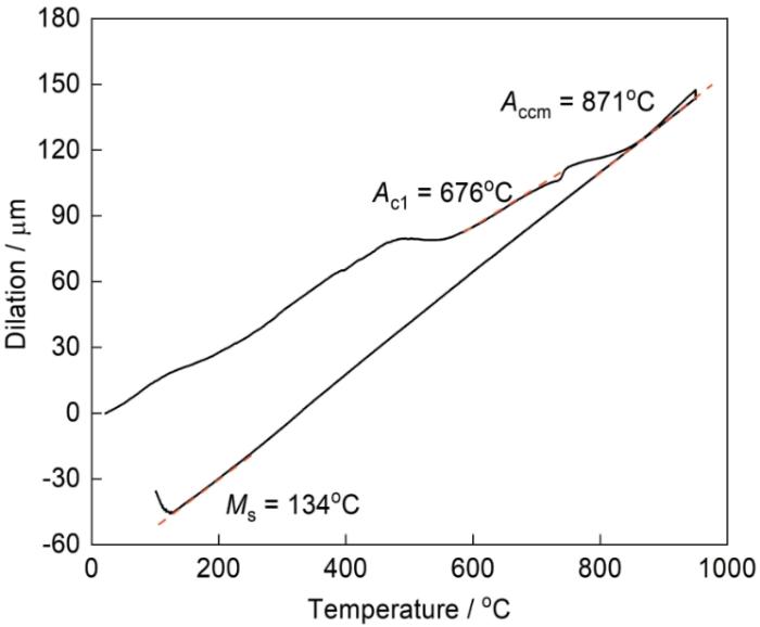
图2给出了等温淬火工艺示意图。将用实验钢盘条制成的拉伸试样粗胚放入热处理炉中,加热至950℃后保温1 h,随后放入盐浴炉中分别等温8、16、48 h,然后空冷至室温,对试样精加工后进行力学拉伸实验。试样的编号分别为230-8 h、230-16 h、230-48 h、270-8 h、270-16 h和270-48 h。
图2

使用TSE 105D型万能试验机按照国家标准《GB/T 228.1-2021金属材料 拉伸实验第一部分:室温试验方法》测试热处理条件不同的纳米贝氏体钢试样的拉伸性能,标准拉伸试样平行段的直径为3 mm (图3),拉伸速率为2.4 mm/min,进行3次测试取其结果的平均值(最大值与最小值差的二分之一为误差棒数值)。
图3

用Apreo 2C型场发射扫描电镜观察热处理后试样的显微组织及断口形貌,并用Oxford Symmetry S2型EBSD探测器表征试样,步长设置为0.15 μm。将从等温淬火试样上切取的厚度为0.3 mm的样品研磨成50 μm厚的薄片,用10%高氯酸酒精溶液对其电解双喷和低温减薄后,用Talos F200S-20型透射电镜观察纳米贝氏体钢组织精细结构。用D8 ADVANCE型Cu靶X射线衍射仪测量不同等温淬火试样的XRD谱中的 (200)γ、(220)γ、(311)γ奥氏体衍射峰和(200)α、(211)α铁素体衍射峰,测量角度范围为40°~102°,步长为0.02°。实验用试样的尺寸为8 mm × 8 mm × 3 mm,将其研磨抛光后用离子刻蚀去除表面应力。依据《YB/T 5338-2006钢中残余奥氏体定量测定》标准测定不同等温淬火工艺试样的残余奥氏体体积分数
式中
式中Cγ 和αγ 分别为残余奥氏体中碳含量和奥氏体点阵参数。
2 实验结果
2.1 纳米贝氏体钢的相变动力学
图4给出了等温淬火工艺不同的实验钢的贝氏体相变曲线。图4a给出了230-48 h和270-48 h的贝氏体膨胀曲线。可以看出,膨胀量的变化曲线呈“S”型,表明在相变开始前有一段孕育期,随后膨胀量缓慢增大直至贝氏体转变停止。随着等温淬火温度的升高,实验钢的贝氏体转变孕育期缩短。图4b给出了230-48 h和270-48 h的贝氏体相变速率。对等温期间贝氏体相变量(膨胀量)求导,可求得每一时刻贝氏体的相变速率。可以看出,230-48 h的相变速率峰值约为3.6 × 10⁻⁴ μm/s,270-48 h的贝氏体相变速率的峰值约为8 × 10⁻⁴ μm/s,约为前者的两倍且其达到峰值的时间缩短了3倍。这表明,等温淬火温度的提高为相变提供了更好的热力学和动力学条件,加速了贝氏体相变。
图4

图4
不同等温淬火工艺实验钢的贝氏体相变曲线
Fig.4
Bainite transformation curves of experimental steel under different austempering treatments (a) Dilation-time curve and (b) Bainite transformation rate-time curve
2.2 热处理对显微组织的影响
图5和图6分别给出了等温淬火工艺不同的实验钢的显微组织和在270℃等温48 h的TEM明场像。可以看出,试样的显微组织由贝氏体铁素体板条(BF)、残余奥氏体(RA)和马氏体(M)组成。由于等温相变温度较低,贝氏体板条极为细小,其尺寸为90 nm~130 nm,其内的高密度位错使纳米贝氏体钢的强度较高[8]。同时,在实验钢中加入的Si(1.5%)抑制了渗碳体的生成。如图6所示,即使在270℃等温48 h的试样中在纳米贝氏体板条内或界面处都没有渗碳体析出。贝氏体板条内过饱和的碳重新分配在周围的过冷奥氏体中,提高了未转变奥氏体的稳定性[3]。等温相变保温结束后,出现两种形貌的过冷奥氏体:一种以块状形式残留在贝氏体束之间(图6a),另一种以薄膜状残留在纳米贝氏体板条间(图6b)。在冷却到室温的过程中,由于薄膜状过冷奥氏体的碳含量较高和具有更高的稳定性,仍以奥氏体的形式保存至室温;而部分块状过冷奥氏体转变成马氏体,一部分残留至室温,即以马氏体和/或奥氏体(M/A岛)的形式存在。
图5

图5
不同等温淬火工艺实验钢的SEM照片
Fig.5
SEM analysis of the experimental steel under different austempering processes (a) 230-8 h, (b) 230-16 h, (c) 230-48 h (d), 270-8 h, (e) 270-16 h, (f) 270-48 h
图6

图6
在270℃等温淬火后实验钢的典型显微组织TEM明场像
Fig.6
TEM bright field image of typical microstructure of experimental steel austempered at 270oC (a) low-magnification TEM image, (b) high-magnification TEM image
图7给出了实验钢在不同温度保温48 h后典型组织的EBSD图。由图7a、c可见,实验钢的组织由不同取向的贝氏体铁素体、残余奥氏体和少量的马氏体组成,贝氏体板条束沿着原奥氏体晶界长大。在230℃等温淬火比在270℃等温淬火试样的贝氏体板条束更细,但是其长度减小。依据显微组织的衬度和EBSD经后处理获得的衍射带衬度对比(BC图),可区分不同的组织。在图7c、d中可见位于原奥氏体晶界和贝氏体板条束间的块状残余奥氏体,而位于贝氏体板条间的薄膜状残余奥氏体因尺寸极小而EBSD无法解析。因此,可根据EBSD结果统计实验钢中面心立方结构(fcc)相分数测出块状残余奥氏体的含量。结果表明,230-48 h和270-48 h试样中的块状残余奥氏体体积分数分别为16.6%和30.4%。
图7
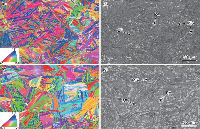
图7
在不同温度淬火等温48h后实验钢局部组织的 EBSD 图
Fig.7
EBSD diagram of local microstructure of experimental steel after isothermal treatment at different quenching temperatures for 48 h (a) IPF diagram of 230-48 h sample, (b) BC diagram of 230-48 h sample, (c) IPF diagram of 270-48 h sample, (d) BC diagram of 270-48 h sample
图8给出了等温淬火工艺不同的实验钢的XRD谱。根据图中(200)γ、(220)γ、(311)γ奥氏体的衍射峰和(200)α、(211)α铁素体的衍射峰,使用
图8
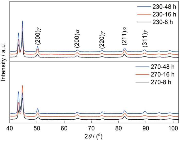
图8
在不同等温淬火后实验钢的XRD谱
Fig.8
XRD patterns of experimental steel after different austempering treatments
表2 在不同等温淬火条件下残余奥氏体的体积分数、残余奥氏体中碳含量和M/A岛的体积分数
Table 2
| Austempering treatments | Volume fraction of retained austenite / % | Carbon content in retained austenite / % | Volume fraction of M/A island / % | |
|---|---|---|---|---|
| Temperature / oC | Time / h | |||
| 230 | 8 | 28.9 ± 2.0 | 1.72 ± 0.041 | 13.56 ± 5.71 |
| 16 | 36.9 ± 2.5 | 1.81 ± 0.022 | 2.15 ± 0.54 | |
| 48 | 41.1 ± 0.8 | 1.80 ± 0.008 | 1.29 ± 0.42 | |
| 270 | 8 | 30.3 ± 5.2 | 1.45 ± 0.059 | 7.99 ± 1.29 |
| 16 | 34.1 ± 0.3 | 1.74 ± 0.039 | 6.36 ± 2.30 | |
| 48 | 45.6 ± 1.8 | 1.73 ± 0.018 | 4.29 ± 0.96 | |
2.3 等温淬火对拉伸性能的影响
图9给出了不同等温淬火工艺实验钢的真应力-应变曲线,其力学性能列于表3。从图9可以看出,真应力-应变曲线没有出现明显的屈服平台,试样的力学性能曲线呈现出连续加工硬化。其原因是,纳米贝氏体钢中的贝氏体板条和薄膜状残余奥氏体互相交替,作为软相的薄膜状残余奥氏体在拉伸时连续变形以缓解应力,作为间隙固溶原子的碳原子由贝氏体扩散到周围的残余奥氏体中而未形成柯氏气团,消除了Lüdes应变和弱化了(Portevin-Le Chatelier) PLC效应。其中230-8h和270-8 h的贝氏体相变程度较低,M/A岛的含量较高和尺寸较大,并且含碳量较低的M/A岛中的残余奥氏体在较低的应力作用下就发生了马氏体相变,不能提高实验钢的塑性;而随着应力的增大新生马氏体导致的应力集中使试样提前脆性断裂。因此,230-8 h和270-8 h试样在未屈服时即断裂,表明其延伸率极低。
图9
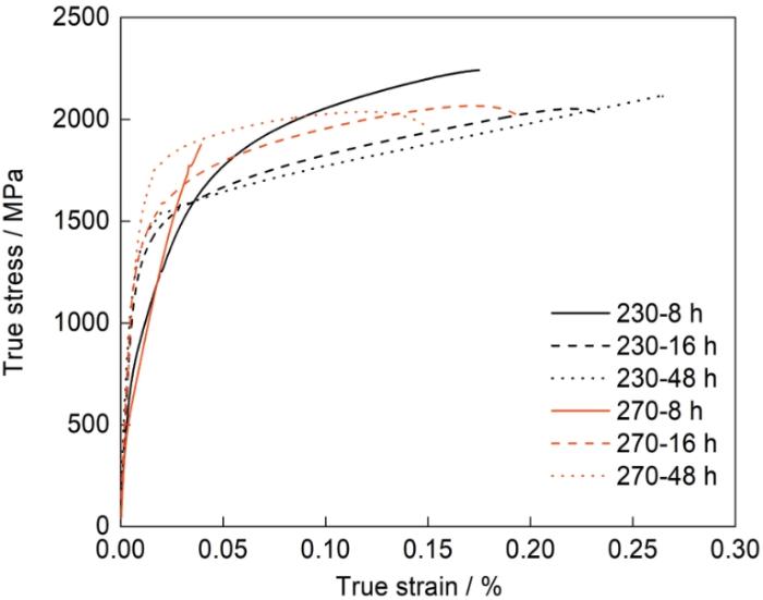
图9
等温淬火工艺不同的实验钢的真应力-应变曲线
Fig.9
True stress-strain curves of experimental steel after different austempering treatments
表3 不同等温淬火工艺实验钢的拉伸性能
Table 3
| Austempering treatments | Tensile strength / MPa | Yield strength / MPa | Elongation / % | |
|---|---|---|---|---|
| Temperature / oC | Time / h | |||
| 230 | 8 | 1872 ± 14.8 | 1220 ± 2.1 | 17.5 ± 0.35 |
| 16 | 1667 ± 0.71 | 1524 ± 23.2 | 27.5 ± 0.71 | |
| 48 | 1625 ± 4.2 | 1505 ± 24.2 | 34.5 ± 3.89 | |
| 270 | 8 | 1804 ± 43.1 | 1771 ± 0.7 | 2 ± 0.1 |
| 16 | 1773 ± 0.7 | 1556 ± 59.8 | 21.5 ± 0.1 | |
| 48 | 1836 ± 0.7 | 1714 ± 1.4 | 18 ± 0.35 | |
由表3可见,对于在230℃等温淬火的试样,随着保温时间的延长其抗拉强度和屈服强度逐渐降低,延伸率逐渐提高(~50%)。屈服强度和抗拉强度降低的原因是,随着贝氏体相变时间的延长材料显微组织中贝氏体的体积分数提高而马氏体的含量降低。延伸率提高的原因是,随着等温时间的延长碳元素不断扩散到残余奥氏体中提高了残余奥氏体的稳定性,有利于相变诱导塑性。而在270℃等温16 h的试样延伸率达到峰值(21.5%),其抗拉强度比等温8 h的试样略有降低(仅31 MPa),但是屈服强度从1771 MPa降低到1556 MPa。其原因是,等温8h试样含有较多的硬质相马氏体(如表2)。随着等温时间延长至48 h,试样的延伸率略有降低(约16%),且其抗拉强度和屈服强度有不同程度的提高。270-48 h试样的组织中含有比270-16 h试样更多的块状残余奥氏体,拉伸时试样中的块状残余奥氏体发生马氏体相变,使组织中的硬质马氏体的体积分数提高[21,22],导致270-48 h试样的抗拉强度和屈服强度提高而延伸率下降。
图10给出了不同等温淬火实验钢的拉伸断口形貌。从图10a~c和g~i可以看出,与传统贝氏体或马氏体钢试样中常见的杯锥状断口的宏观形貌不同,试验钢拉伸试样断口的宏观形貌没有明显的放射区。随着钢延伸率的提高,断口的颈缩程度提高。在试样断口的表面出现明显的凹凸不平的撕裂棱。这种具有吸能性能的撕裂棱其尺寸在断裂时沿着裂纹拓展的方向逐渐增大,有利于韧性的提高[20]。从图10d~f和j~l可以看出,断口上均有不同大小的韧窝和孔洞,是典型的纤维区特征。保温230-8 h和270-8 h的试样其端口形貌为韧窝和断裂小平面,表现出韧性和脆性的混合型断裂特征(图10d和10j)。随着等温时间的延长断口形貌逐渐转变为较大的韧窝和小解理平面,更加起伏不平并产生二次裂纹,表现出准解理断裂的特征(图10e、f、k和l),表明其韧性提高。
图10
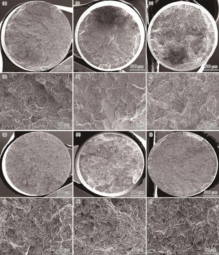
图10
不同等温淬火工艺实验钢的拉伸断口SEM照片
Fig.10
SEM analysis of experimental steel under different austempering treatment (a, d) 230-8 h, (b, e) 230-16 h, (c, f) 230-48 h, (g, j) 270-8 h (h, k) 270-16 h, (i, l) 270-48 h
残余奥氏体是高强贝氏体钢中的韧化相,其稳定性直接影响相变诱导塑性效果,从而影响材料的塑性,而残余奥氏体的数量、碳含量、微观形貌等影响其稳定性。在230℃等温48 h的样品,其抗拉强度和屈服强度分别为1625和1505 MPa,延伸率达到34.5%,其强韧性匹配良好。其原因是,在270℃等温48h有利于贝氏体相变过程中碳的配分,更容易生成大尺寸富碳的脆硬M/A岛,使抗拉强度和屈服强度较高但是延伸率显著降低。而在230℃等温淬火,随着保温时间由8 h延长至48 h薄膜状残余奥氏体的体积分数由6.3%提高到24.5%。这种位于贝氏体板条间的残余奥氏体的表面积更大,在大应变条件下更有利于相变诱导塑性的提高,从而推迟颈缩的产生,最终使材料的延伸率提高,使材料在具有高强度的同时具有较高的塑性。
3 结论
(1) 本文设计的这种可制造钢丝的纳米贝氏体钢Fe-0.8C-2Mn-1.5Si-1.5Cr-0.25Mo-0.25Ni-1Al-0.25Co-0.1V,其显微组织由贝氏体铁素体、残余奥氏体和少量马氏体组成。随等温淬火温度的提高相变速率提高、贝氏体体积分数提高和过冷奥氏体含量减少,在室温下得到的块状M/A岛的尺寸减小和体积分数降低。随着等温时间的延长,碳的配分和贝氏体体积分数的提高使残余奥氏体稳定性提高且残余奥氏体中的碳含量呈上升趋势,过冷奥氏体更加稳定,冷却至室温得到的M/A岛中脆性马氏体比例大幅度降低。
(2) 这种纳米贝氏体钢的抗拉强度和屈服强度与纳米贝氏体钢组织中贝氏体与马氏体含量相关,贝氏体板条数目越多和硬质马氏体减少使材料抗拉强度降低。残余奥氏体的稳定性影响纳米贝氏体钢的延伸率。随着保温时间的延长碳原子从贝氏体板条中配分至其周围残余奥氏体中的碳含量提高,提高了残余奥氏体的稳定性而使延伸率提高。
(3) 这种钢在230℃等温淬火保温48 h后,其抗拉强度和屈服强度分别为1625和1505 MPa,延伸率达到34.5%,具有最佳的强塑性匹配。
参考文献
Development of nanostructured bainite transformation acceleration technology
[J].
The development of nanostructured bainite makes it possible to refine the microstructure of steel materials at the nanometer level under conventional conditions. However, the thermal dynamics conditions in the low temperature transition of austenite limit the transformation rate of nanostructured bainite and hinder the corresponding alloying development and industrial application. The acceleration technics of nanostructured bainite transformation developed by scholars, especially on conditions of chemical composition, pretransformation, predeformation, and strong magnetic field were reviewed. The comprehensive analysis shows that bainite nucleation and growth should be separately considered for nanobainite transformation. The design of nanostructured bainite alloy and process should fully consider the different effects of various factors on the two processes, and optimize the transformation kinetics and microstructure of bainite at the same time. Composite phase transformation acceleration technic may be a new direction for the development of nanostructured bainite steels.
纳米贝氏体钢相变加速技术开发进展
[J].
The first bulk nanostructured metal
[J].
Tensile behaviour of a nanocrystalline bainitic steel containing 3wt% silicon
[J].
Nanostructured bainite
[J].
Microstructural effects on the sub-critical fatigue crack growth in nanobainite
[J].
Microstructural transformation and plasticity mechanism of 2 GPa medium-carbon medium-manganese nano-bainitic steel
[J].
2 GPa中碳中锰纳米贝氏体钢的相变和塑性机理
[J].
Thermal stability of nanoscale bainite/martensite steel
[J].
纳米贝氏体/马氏体钢的热稳定性
[J].
Deformation mechanisms in nanostructured bainitic steels under torsion
[J].
Thermal stability of retained austenite in TRIP steels studied by synchrotron X-ray diffraction during cooling
[J].
Effect of fresh martensite on the stability of retained austenite in quenching and partitioning steel
[J].
Grain size effects in multiphase steels assisted by transformation-induced plasticity
[J].
On structure-property relationship in nanostructured bainitic steel subjected to the quenching and partitioning process
[J].
Toughness variations in nanostructured bainitic steels
[J].
Improvement of strength-toughness combination in nanostructured bainite
[A].
Design of novel bainitic steels: moving from ultrafine to nanoscale structures
[J].
Effect of electropulsing on nanostructured bainitic steel
[J].
In-situ observations of lattice parameter fluctuations in austenite and transformation to bainite
[J].
Carbon clustering in low-temperature bainite
[J].
Ductilization of high carbon, high silicon carbide-free nanostructured bainitic steel
[J].
Tensile response of two nanoscale bainite composite-like structures
[J].
Effect of pre-existed austenite on austenite reversion and mechanical behavior of an Fe-0.2C-8Mn-2Al medium Mn steel
[J].
Strain induced martensitic transformation of Fe-20Cr-5Mn-0.2Ni duplex stainless steel during cold rolling: Effects of nitrogen addition
[J].
