


刘畅等[4]进行CTOD试验研究E36钢埋弧焊焊缝金属的断裂韧性时发现,针状铁素体使裂纹尖端塑性变形而钝化,其断裂韧性显著高于先共析铁素体,焊缝金属的CTOD值为0.333~1.328 mm。显微组织分布的不均匀性,是CTOD值波动的主要原因。Barbosa等[5]进行CT试验研究E36钢埋弧焊焊缝金属的疲劳裂纹扩展速率时发现,针状铁素体使裂纹表面的粗糙度提高,诱导裂纹闭合和降低裂纹扩展速率。Yang等[6]研究X80钢埋弧焊焊缝金属的断裂韧性时发现,粗大的魏氏体显著降低断裂韧性而使焊缝金属的CTOD值仅为0.2427 mm。这表明,不同强度高强钢焊缝金属的断裂韧性有较大的差异。鉴于此,本文使用一种Si-Mn-Ni气保护实心焊丝进行MAG焊,通过系列温度冲击试验、疲劳裂纹扩展速率试验和裂纹尖端张开位移试验研究焊缝金属的断裂韧性和显微组织对断裂韧性的影响。
1 实验方法
表1 试板和焊丝的化学成分
Table 1
| Material | C | Si | Mn | Ni | Cr+Cu | Ti | P | S | Other |
|---|---|---|---|---|---|---|---|---|---|
| Test panel | < 0.06 | < 0.30 | 1.10 | 0.20 | 0.450 | < 0.03 | ≤ 0.005 | ≤ 0.005 | Trace |
| Solder wire | 0.039 | 0.49 | 1.46 | 1.02 | 0.391 | 0.019 | ≤ 0.005 | ≤ 0.005 | Trace |
表2 试板和焊缝金属的力学性能
Table 2
| Material | Yield strength Rp0.2 / MPa | Tensile strength Rm / MPa | Elongation after fracture A / % | Reduction of Area Z / % | Poisson's ratio μ | Elastic modulus E / GPa |
|---|---|---|---|---|---|---|
| Test panel | 552 | 619 | 24.5 | 76 | - | - |
| Weld metal | 538 | 593 | 24.0 | 78 | 0.3 | 212 |
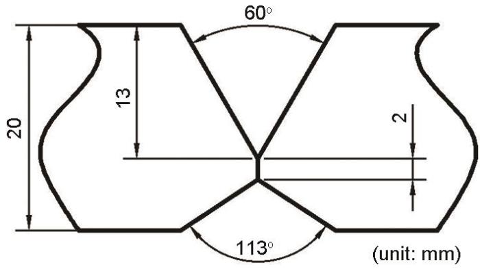
图1
用体积分数为2%的硝酸酒精溶液腐蚀金相试样。用Olympus GX51型光学显微镜(OM)观察焊缝金属的显微组织。用Lepera溶液腐蚀后,用同型OM观察焊缝金属中的M-A组元。使用ImageJ软件统计M-A组元的含量和尺寸。用EM500-2A型半自动显微维氏硬度仪测试M-A组元和铁素体基体的显微硬度,载荷力为1.96 N,加载时间为10 s。将透射电镜试样用砂纸手工减薄至40~50 μm,然后用磁力减薄器进行电解双喷减薄,双喷溶液是体积分数为4%的高氯酸酒精溶液,温度为-35 ± 5℃。用H-800型透射电镜(TEM)观察焊缝金属的精细组织,观察位置在图2a中给出。
图2
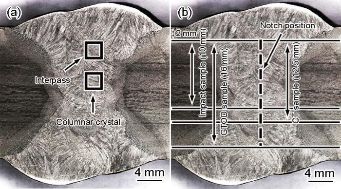
图2
组织观察和性能测试位置的示意图
Fig.2
Location diagram of organization observation and performance test (a) organization observation, (b) performance tests
依据国家标准GB/T 2650-2008进行焊缝金属的系列温度冲击试验,V型标准试样的尺寸为10 mm × 10 mm × 55 mm。依据国家标准GB/T 6398-2017进行焊缝金属的疲劳裂纹扩展速率(CT)试验,试样的尺寸为60 mm× 62.5 × 12.5 mm,如图3a所示,试验设备为MTS 370.10疲劳试验机,试验温度为25℃,加载频率为25 Hz,载荷比R为0.1,加载波形为正弦波,试验过程中保持载荷恒定,最大恒幅载荷Pmax为13、15和17 kN,使用降K法预制疲劳裂纹,用柔度法测量裂纹扩展起始长度为a0和终止长度为af,用七点递增多项法计算疲劳裂纹扩展速率da/dN;依据国家标准GB/T 21143-2014进行焊缝金属的裂纹尖端张开位移(CTOD)试验,试样为直三点弯曲标准试样,尺寸为150 mm × 32 mm × 16 mm (图3b),试验温度为25℃,试验前先使用200 kN高频疲劳试验机预制疲劳裂纹,之后在MTS EL0057疲劳试验机上进行CTOD试验。用九点值法测量初始裂纹长度和终止裂纹长度,并根据标准BS7448计算CTOD值。不同性能测试试样的缺口位置均为焊缝金属的中心(图2b中虚线)。用Quanta 650型扫描电镜(SEM)观察试样断口的形貌。
图3
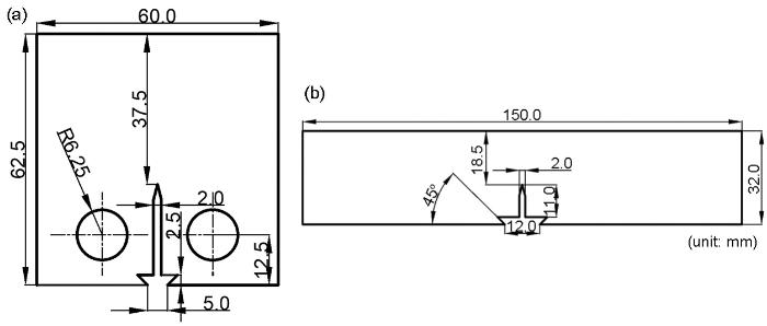
图3
CT试样和CTOD试样尺寸的示意图
Fig.3
Dimension diagram of CT sample and CTOD sample (a) CT sample, (b) CTOD sample
2 实验结果
2.1 焊缝金属的组织
图4给出了焊缝金属组织的照片。在图4中能依稀观察到柱状晶的原奥氏体晶界(PCGB),主要由细小交织状的针状铁素体(AF)组成(图4a);AF板条多数为细小的短棒状,板条之间基本上呈交织状分布,板条的宽度集中在0.30~1.25 μm。交织状分布把板条长大粗化所需的区域分割成许多细小的区域,使板条只能在这些细小的区域内长大,从而使板条细化(图4b);焊道间的组织由准多边形铁素体(QF)和少量的AF组成(图4c);QF板条内的位错密度较高,QF板条多为块状且显著粗化,板条的宽度集中在0.88~3.81 μm(图4d)。在多层多道焊接程中先焊道受后焊道类似于焊接热循环的再热作用,当再热作用的峰值温度达到1000℃左右时先焊道的部分原柱状晶AF转变为QF,在部分QF中保留AF的大角度晶界[7]。
图4
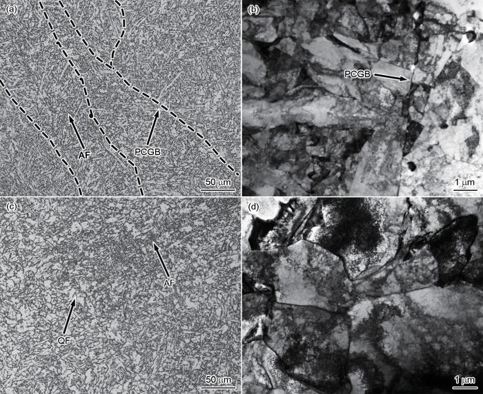
图4
焊缝金属组织照片
Fig.4
Photos of weld metal microstructure (a) columnar crystal (OM), (b) columnar crystal (TEM), (c) interpass (OM), (d) interpass (TEM)
图5
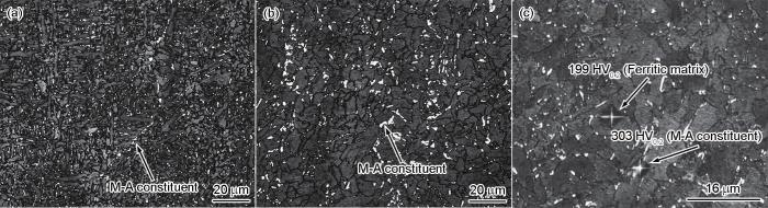
图5
焊缝金属中的M-A组元及其显微硬度照片
Fig.5
Photos of M-A constituent and microhardness in weld metal (a) columnar crystal, (b) interpass, (c) microhardness
2.2 系列温度冲击吸收功
表3列出了焊缝金属的系列温度冲击吸收功。可以看出,随着冲击温度的降低冲击吸收功随之降低,在20℃到-40℃和-60℃到-80℃范围内冲击吸收功降低趋势比较平缓,但是在-40℃~60℃冲击吸收功急剧降低,平均冲击吸收功从154.3 J降低到21.7 J。这表明,焊缝金属的韧脆转变温度在-40℃与-60℃之间。
表3 系列温度冲击吸收功
Table 3
| Temperature | 20oC | 0oC | -20oC | -40oC | -60oC | -80oC |
|---|---|---|---|---|---|---|
| Absorbed energy / J | 188.3 | 181.3 | 157.3 | 154.3 | 21.7 | 11.2 |
使用Boltzmann函数
能较好地拟合冲击吸收功与冲击温度之间的关系,其拟合结果残差较小和拟合优度较高[8]。
每组冲击试样的冲击吸收功有一定的离散性,所以选择平均冲击吸收功进行Boltzmann函数拟合(图6)。拟合结果表明,焊缝金属的韧脆转变温度约为-48.4℃,拟合相关系数R2为0.9601。
图6
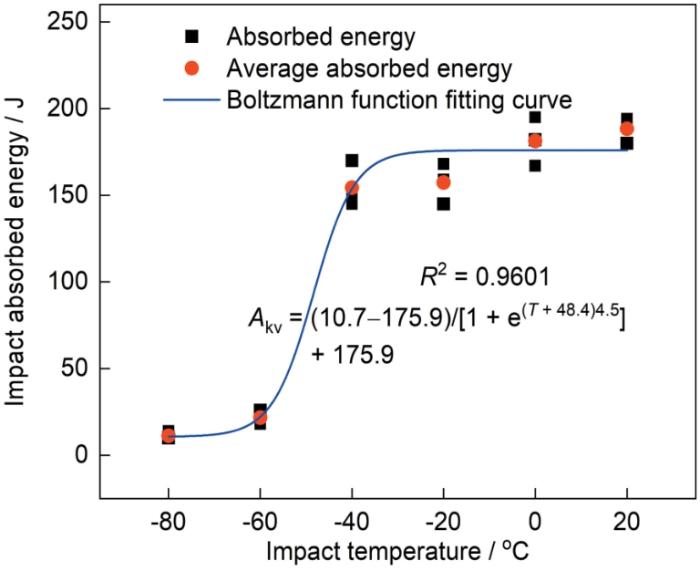
图7
2.3 疲劳裂纹的扩展速率(CT)
Paris公式[9]定量描述了金属材料的疲劳裂纹稳定扩展阶段中裂纹的扩展速率da/dN与应力强度因子范围ΔK之间的关系,ΔK为疲劳裂纹扩展驱动力
计算。
图8给出了焊缝金属在不同恒幅载荷下的a-N曲线和da/dN-ΔK曲线,试验结果列于表4。由图8a可见,随着载荷循环次数N的增大疲劳裂纹长度a呈指数增长且增长速率不断提高。另外,随着恒幅载荷的增大载荷循环次数N减小,从426456次减小到112577次,表明疲劳寿命不断降低。由图8b可见,不同恒幅载荷下的da/dN-ΔK曲线斜率基本一致,拟合结果表明恒幅载荷为13 kN、15 kN和17 kN的C值分别为2.6841 × 10⁻⁹、2.1048 × 10⁻⁹和2.8874 × 10⁻⁹,m值分别为3.1678、3.2118和3.0869,C与m的差异较小;随着ΔK的增大da/dN随之增大,但是当ΔK相同时da/dN总体上随着恒幅载荷的增大而减小。随着恒幅载荷的增大疲劳裂纹尖端的塑性区逐渐扩大,而塑性区中疲劳裂纹的闭合和钝化使疲劳裂纹的扩展速率降低。
图8
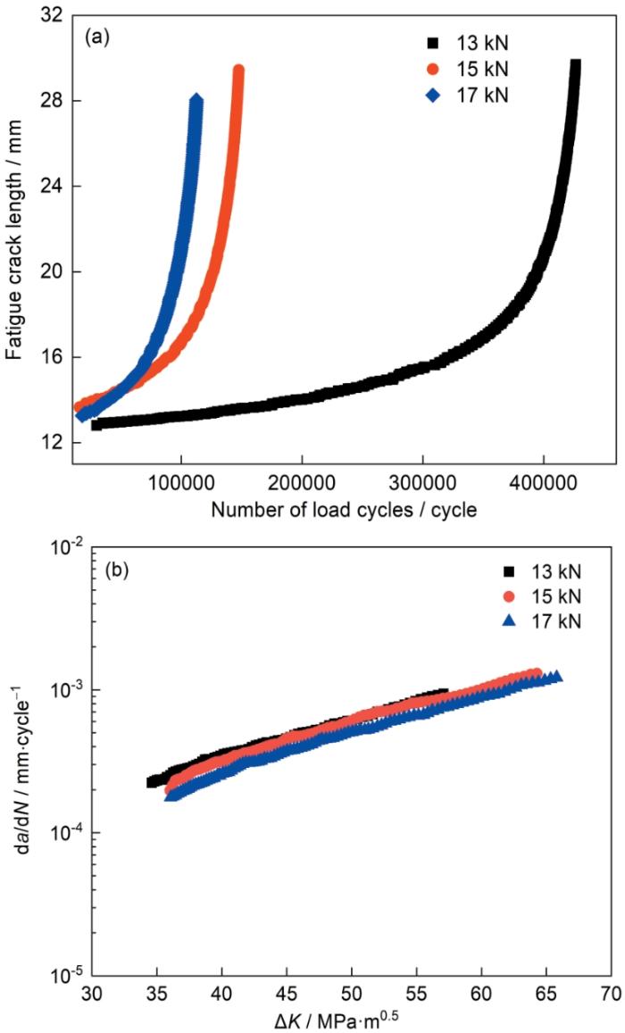
图8
不同恒幅载荷下的a-N曲线和da/dN-ΔK曲线
Fig.8
a-N curve and da/dN-ΔK curve for different constant amplitude loads (a) a-N curve, (b) da/dN-ΔK curve
表4 疲劳裂纹扩展速率试验结果
Table 4
| Pmax / kN | a0 / mm | af / mm | N / cycle | C | m | R2 | da/dN-ΔK |
|---|---|---|---|---|---|---|---|
| 13 | 12.8064 | 29.7039 | 426456 | 2.6841 × 10⁻⁹ | 3.1678 | 0.9830 | 2.6814 × 10⁻⁹ (ΔK)3.1678 |
| 15 | 13.6590 | 29.4438 | 147585 | 2.1048 × 10⁻⁹ | 3.2118 | 0.9898 | 2.1048 × 10⁻⁹ (ΔK)3.2118 |
| 17 | 13.2626 | 28.0428 | 112577 | 2.8874 × 10⁻⁹ | 3.0869 | 0.9984 | 1.8856 × 10⁻⁹ (ΔK)3..0869 |
图9
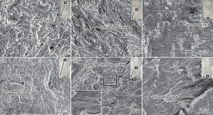
图9
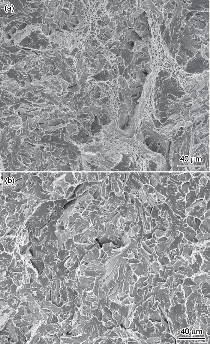
不同恒幅载荷下的断口形貌
Fig.9
Fracture morphology for different constant amplitude loads (a) ealy stage of 13 kN, (b) intermediate stage of 13 kN, (c) later stage of 13 kN, (d) ealy stage of 17 kN, (e) intermediate stage of 17 kN, (f) later stage of 17 kN
2.4 疲劳裂纹尖端的张开位移(CTOD)
表5 初始裂纹的长度 (mm)
Table 5
| Sample | a01 | a02 | a03 | a04 | a05 | a06 | a07 | a08 | a09 |
|---|---|---|---|---|---|---|---|---|---|
| 1 | 14.21 | 15.98 | 16.71 | 16.75 | 16.38 | 15.86 | 16.08 | 16.31 | 16.07 |
| 2 | 14.92 | 16.14 | 16.88 | 17.14 | 17.09 | 16.86 | 16.18 | 16.11 | 15.83 |
| 3 | 16.49 | 16.67 | 16.46 | 16.71 | 17.27 | 17.47 | 17.26 | 16.26 | 14.42 |
| 4 | 15.52 | 16.71 | 17.41 | 17.65 | 17.53 | 17.07 | 16.48 | 16.30 | 16.03 |
| 5 | 16.47 | 16.72 | 16.25 | 16.22 | 16.45 | 16.93 | 17.03 | 16.60 | 15.55 |
| 6 | 17.20 | 17.36 | 16.85 | 16.69 | 17.04 | 16.86 | 17.46 | 16.90 | 15.58 |
表6 终止裂纹的长度 (mm)
Table 6
| Sample | a1 | a2 | a3 | a4 | a5 | a6 | a7 | a8 | a9 |
|---|---|---|---|---|---|---|---|---|---|
| 1 | 15.07 | 16.63 | 17.62 | 17.90 | 17.90 | 17.05 | 16.90 | 16.58 | 16.21 |
| 2 | 15.09 | 16.43 | 17.41 | 17.60 | 17.62 | 17.30 | 16.63 | 16.23 | 15.98 |
| 3 | 16.54 | 16.86 | 16.89 | 17.39 | 17.84 | 17.98 | 17.68 | 16.55 | 14.95 |
| 4 | 16.30 | 17.05 | 18.10 | 18.28 | 18.24 | 17.70 | 17.18 | 16.50 | 16.12 |
| 5 | 16.59 | 17.01 | 17.02 | 17.50 | 17.94 | 17.82 | 17.59 | 17.03 | 16.06 |
| 6 | 17.30 | 17.67 | 17.45 | 17.90 | 18.34 | 18.05 | 17.86 | 17.25 | 16.06 |
和
计算了原始裂纹长度a0和裂纹稳定扩展量Δa[10]。
根据BS7748标准,CTOD值为
W为试样宽度,B为试样厚度,a0为原始裂纹长度,F为循环载荷,S为试样跨度,Vp为塑性分量,δys为屈服强度,v为泊松比,E为弹性模量,Z为刀口厚度。
表7列出了CTOD的试验结果,可见a0/W为0.503~0.530,任何2个裂纹深度的差值都小于0.177a0,全部裂纹测试点的最大和最小之差值不超过0.095W,满足GB/T 21143-2014所规定的有效要求,因而CTOD试验结果有效。Δa为0.391~0.876 mm,δ为0.481~0.781 mm,δ的平均值为0.6002 mm。
表7 CTOD的试验结果
Table 7
| Sample | W / mm | B / mm | S / mm | Z / mm | a0 / mm | Δa / mm | F / kN | Vp / mm | δ / mm |
|---|---|---|---|---|---|---|---|---|---|
| 1 | 32.07 | 15.85 | 128 | 0 | 16.151 | 0.876 | 29.222 | 3.395 | 0.781 |
| 2 | 32.08 | 15.90 | 128 | 0 | 16.447 | 0.391 | 27.781 | 1.995 | 0.481 |
| 3 | 32.08 | 15.92 | 128 | 0 | 16.694 | 0.422 | 27.03 | 2.201 | 0.516 |
| 4 | 32.13 | 15.93 | 128 | 0 | 16.866 | 0.542 | 26.649 | 2.488 | 0.567 |
| 5 | 32.16 | 15.95 | 128 | 0 | 16.526 | 0.753 | 27.712 | 2.987 | 0.661 |
| 6 | 32.13 | 15.91 | 128 | 0 | 17.019 | 0.631 | 26.088 | 2.672 | 0.595 |
图10给出了焊缝金属的δ-Δa阻力曲线。可以看出,在总体上,随着Δa的增大δ随之增大。δ-Δa阻力曲线的拟合方程为
图10
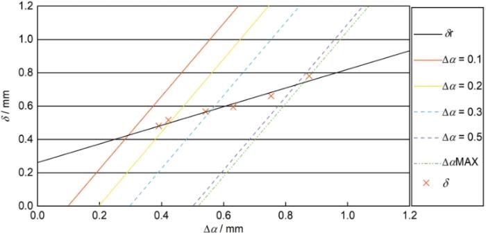
拟合优度R为0.9870。根据国家标准GB/T 21143-2014测得焊缝金属的有效特征值δ0.2BL为0.5103 mm,满足Offshore Standard DNV-OS-C401规定的δ> 0.15 mm的技术指标。
试样CTOD值δ的离散性影响焊缝金属的断裂韧性:(1) 如果CTOD平均值大于0.15 mm,但离散性较大,使安全系数降低;(2) 如果CTOD值δ的最小值大于0.15 mm,安全系数较高但离散性较大,则使焊接成本提高。由表7可见,CTOD值δ为0.481~0.781 mm,平均值为0.6002 mm,离散系数(标准差/平均值)仅为16.5%。离散系数较小,表明使用所研焊丝的焊缝金属的断裂韧性良好。
图11
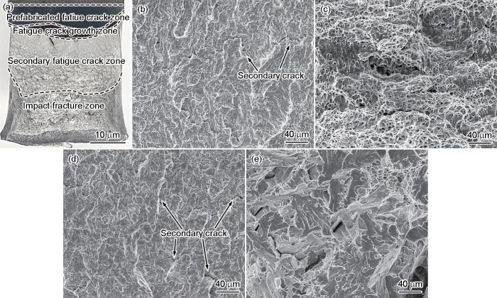
图11
CTOD试样断口的形貌
Fig.11
Fracture morphology of CTOD sample (a) micromorphology, (b) prefabricated fatigue crack zone, (c) fatigue crack growth zone, (d) secondary fatigue crack zone, (e) impact fracture zone
2.5 显微组织对断裂韧性的影响
图12
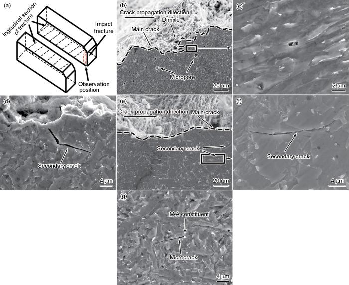
图12
-40℃冲击断口纵剖面上的裂纹扩展形貌
Fig.12
Crack propagation morphology on the longitudinal section of the imapact fracture at -40oC (a) schematic diagram of observation position, (b) effect of AF on main crack growth, (c) high magnification image of the area in Fig.b, (d) secondary crack propagation in AF, (e) effect of QF on crack growth; (f) high magnification image of the area in Fig.e, (g) M-A constituent induced microcrack
AF多为大角度晶界(50°~60°),不利于裂纹扩展[12]。另外,AF板条呈交织状分布(图4b),使断裂过程中形成的微裂纹难以在交织状板条间快速贯穿连续扩展而发生转向,使微裂纹扩展路径增长。同时,交织状板条使板条束细化,进一步增加;大角度晶界的数量[13],使阻碍裂纹扩展能力显著增大,和裂纹尖端易钝化和扩展方向易偏转,最终使裂纹扩展路径的曲折程度显著增大和裂纹扩展所需的能量显著增大,提高了断裂韧性。此外,AF的塑性变形不仅减小了断裂过程中基体的局部应力集中和微裂纹的形成,而且抑制了微孔长大,从而减少微孔相互连接形成裂纹[13]。同时,显著的塑性变形有利于在冲击断口表面形成大量韧窝,使冲击吸收能量显著增大。这表明,AF阻碍裂纹扩展的能力强,有利于提高断裂韧性。
由图12e、f可见,与柱状晶AF相比,焊道间QF的主裂纹(虚线)扩展方向偏转次数显著减少,使裂纹扩展路径曲折度显著减小,即裂纹扩展路径趋于平直和长度减小。同时,在基体中形成了许多二次裂纹,且以近直线状在QF中扩展,表明QF阻碍裂纹扩展能力较弱。QF的位错密度较高[8],在断裂过程中位错运动发生增殖和缠结并在晶界、析出相和M-A组元等处发生塞积。这导致位错塞积前端产生高度的应力集中并快速达到原子键合力而利于裂纹扩展[15],粗大的块状QF板条也有利于微裂纹快速贯穿连续扩展(图4d);此外,先焊道受后焊道的再热作用,使部分原柱状晶AF转变为焊道间QF等再热组织,成为多层多道焊缝金属的韧性薄弱环节。焊道间再热组织所占比例越大,相应的韧性越低[16]。这表明,QF较弱的阻碍裂纹扩展能力,使断裂韧性降低。
3 结论
(1) 对440 MPa级高强钢进行MAG焊,其焊缝金属的韧脆转变温度约为-48.4℃。随着冲击温度的降低,冲击断口的形貌从韧窝+准解理断裂向解理断裂转变。
(2) 随着恒幅载荷(13~17 kN)的增大,载荷循环次数N和疲劳寿命减小;对于相同的应力强度因子范围ΔK,疲劳裂纹扩展速率da/dN随着恒幅载荷的增大而减小。
(3) 焊缝金属的CTOD值δ为0.481~0.781 mm,有效特征值δ0.2BL为0.5103 mm,CTOD值δ离散系数仅为16.5%,表明焊缝金属的断裂韧性良好。
(4) 柱状晶由针状铁素体和少量M-A组元组成,焊道间由准多边形铁素体、少量针状铁素体和M-A组元组成;针状铁素体较强的阻碍裂纹扩展能力使断裂韧性提高,但是准多边形铁素体阻碍裂纹扩展能力较弱和M-A组元易诱发微裂纹,使断裂韧性降低。
参考文献
Effect of titanium addition on the microstructure and inclusion formation in submerged arc welded HSLA pipeline steel
[J].
Effect of heat input on low temperature toughness and corrosion resistance of Q1100 steel welded joints
[J].
热输入对Q1100钢焊接接头低温韧性及耐蚀性能的影响
[J].
Effect of heat input on microstructure and performance of welded joint in 1000 MPa grade steel for construction machinery
[J].
热输入对1000 MPa级工程机械用钢接头组织性能的影响
[J].
采用三种热输入进行1 000 MPa级控轧控冷(Thermo mechanical control process, TMCP)高强钢的熔化极气体保护焊,利用金相显微镜、扫描电子显微镜和透射电子显微镜研究热输入对焊接接头组织和力学性能的影响。研究结果表明,三种热输入焊缝金属组织主要由板条马氏体和板条贝氏体为主、并含有少量残余奥氏体和粒状贝氏体;焊接热影响区粗晶区组织以板条马氏体和贝氏体为主,并含有少量粒状贝氏体。随着热输入的增加,焊缝组织中贝氏体板条粗化,马氏体板条减少,而粒状贝氏体逐渐增多,部分膜状残余奥氏体向块状转变;焊缝金属冲击韧度和硬度、接头强度逐渐降低,而接头热影响区冲击韧度先增后降;当热输入为15 kJ/cm时焊接接头强韧性匹配最佳。
Critical fracture toughness of weld metal structure in submerged arc welding of EH36 steel
[J].
EH36钢埋弧焊焊缝金属组织临界断裂韧性
[J].
Fatigue crack growth rates on the weld metal of high input submerged arc welding
[J].
Fracture toughness of the materials in welded joint of X80 pipeline steel
[J].
Strengthening and toughening mechanisms of deposited metals for 420 MPa weathering bridge steel
[J].
420 MPa级耐候桥梁钢用焊材熔敷金属强韧化规律
[J].
Study on the toughening mechanism of 400 MPa grade low alloy high strength steel welding materials
[D].
400 MPa级低合金高强钢焊接材料强韧化机理研究
[D].
Fracture behavior of thick X80 pipeline steel plates at -25oC
[J].
厚规格X80管线钢低温断裂行为研究
[J].
Effects of local-brittle-zone(LBZ) microstructures on crack initiation and propagation in three Mo-added high-strength low-alloy
[J].
Influence of shielding gas composition on microstructure characteristics of 1000 MPa grade deposited metals
[J].In recent years, high and ultra-high strength steels have been developed and used in light-weight constructions such as the structural members of mobile equipment in order to reduce weight and fabrication costs and to enhance the performance. Welding of steels with yield strength of more than 900 MPa is particularly challenging because of the toughness requirements for the weld metal, which calls for welding consumables of high strength and good toughness. Weld metals have been produced for a variety of welding methods with yield strength up to or above 1000 MPa, but their impact toughness remained only at medium yield strengths. Proper microstructure is the key to meeting this requirement, and its final microstructure depends on the chemical composition and cooling rate. For the deposited metal produced by gas metal arc welding (GMAW), the composition is dependent on the welding wire and shielding gas. The cooling rate of the weld metal is controlled by a combination of heat input and heat extraction. It is known that the addition of CO2 to argon based shielding gas is effective for improvement of productivity in GMAW welding of steel. Through the chemical reaction in the welding arc, CO2 in the shielding gas can affect the chemical composition of the weld metal, and its microstructure. The 1000 MPa grade deposited metals was welded with GMAW, and the effects of shielding gas composition (Ar+(5%~30%)CO2, volume fraction) on the general compositional and microstructural characteristics of deposited metals, including nonmetallic inclusions, were experimentally characterized with SEM, EBSD and TEM. The microstructure of the deposited metals is mainly composed of martensite and bainite. With the increase of CO2 content (5%~30%), the strength of the deposited metals decrease slightly and the impact toughness increases first and then decreases. Meanwhile, the transformation range (B50-Ms) of the deposited metal increases, the bainite content increases (8%~29.6%) with the quantity of inclusions that are suitable for bainite nucleation increases, and the nucleation position changes from the original austenite grain boundary to the common nucleation on the original austenite grain boundary and inclusions within the grain. At the same time, the microstructure morphology of the deposited metal changes from parallel to intertexture, which presented an intersected configuration and microstructure refinement.
保护气成分对1000 MPa级高强熔敷金属组织特征的影响
[J].通过附带EDS的FEGSEM、EBSD、TEM等实验方法,研究了保护气成分(Ar+5%CO<sub>2</sub>、Ar+10%CO<sub>2</sub>、Ar+20%CO<sub>2</sub>、Ar+30%CO<sub>2</sub>,体积分数)对1000 MPa级高强熔敷金属组织特征的影响,阐明了保护气成分对组织转变的影响机制。结果表明,随着保护气中CO<sub>2</sub>含量增加,1000 MPa级熔敷金属强度略有下降,而冲击韧性先升高后降低。不同保护气熔敷金属均由马氏体/贝氏体混合组织及板条间残余奥氏体组成。随着保护气中CO<sub>2</sub>含量增加,熔敷金属中贝氏体相变体积分数为50%时的温度(B<sub>50</sub>)与马氏体相变开始温度(M<sub>s</sub>)相变温度区间增大,适宜贝氏体形核的夹杂物数量增多,随贝氏体含量(体积分数)由8%增加到29.6%,其形核位置从原始奥氏体晶界向原始奥氏体晶界及晶内夹杂物处共同形核转变,熔敷金属组织形貌由“平行状”向“交织状”转变,分割细化组织,有利于高强熔敷金属强韧性的改善。
Influence of microstructural aspects on impact toughness of multi-pass submerged arc welded HSLA steel joints
[J].
