


1 实验方法
1.1 样品的制备
实验用CLAM钢的型号为HEAT-1506,材料,其化学成分列于表1。
表1 CLAM钢的化学成分(质量分数,%)
Table 1
| Elements | C | Cr | W | V | Mn | Ta | Ni | Si | S | P | Fe |
|---|---|---|---|---|---|---|---|---|---|---|---|
| Content | 0.12 | 8.9 | 1.44 | 0.20 | 0.35 | 0.15 | 0.02 | 0.08 | 0.003 | <0.0005 | Bal. |
焊前在5 mm厚的焊件上开一个60° V形坡口,用无水乙醇和丙酮对坡口及其两侧充分清洗以去除表面的油污。实验中进行手工钨极氩弧焊(TIG焊),焊接参数为:电压12 V,打底焊电流为120 A,盖面焊电流为125 A,氩气流量10 L·min-1,焊接速度1 mm·s-1。为了消除焊后残余应力和焊接变形得到良好的焊缝金属组织,对部分焊板进行焊后调质处理[8](980℃/0.5 h淬火(水冷)+760℃/2 h回火(空冷))。垂直于焊缝区域切下尺寸为10 mm×8 mm×2 mm的试样,用于观察辐照后表面形貌和纳米压痕测试,尺寸为10 mm×10 mm×0.5 mm的试样用于透射电镜观察。将试样表面研磨和机械抛光至镜面,超声洗净吹干后用于离子辐照实验。
1.2 离子辐照实验
图1
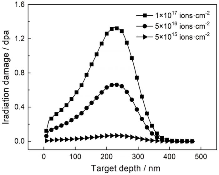
图1
辐照损伤量随离子注入深度的变化曲线
Fig.1
Variation curve of irradiation damage with ion implantation depth
1.3 性能表征
用型号为FEI Nova Nano 450的扫描电子显微镜(SEM)观察辐照前后CLAM钢焊缝的表面形貌,用FEI tecnai-F20型透射电镜表征辐照前焊态和调质处理态焊缝的微观组织和离子辐照后焊缝微观组织(位错环、氦泡)。用于透射电镜观察的透射试样厚度约为50 nm且辐照面不能受到破坏,故使用Gatan PIPS II离子减薄仪将试样单面减薄至所要求厚度。使用SRIM软件模拟辐照损伤层的厚度。用纳米压痕技术,即通过计算机程序控制载荷发生连续变化实时测量压痕深度[10]。仪器的型号为Agilent Nano Indenter G200,用Berkovich三棱锥型压头,载荷分辨率为50 nN,应变速率为0.05-1。用CSM连续刚度测试,每个样品选取8个测试点,每点的最大压入深度为1000 nm,对有效数据做均值化处理。
2 结果和讨论
2.1 辐照后表面形貌的变化
图2给出了辐照后焊态和调质处理态焊缝表面形貌放大10000倍的SEM照片。由图1a,b可以看出,辐照前两种焊缝的表面均比较光滑,受到不同剂量的He+轰击后焊缝表面出现的尺寸和数量不等的孔洞。辐照剂量较小时焊缝表面零散分布着尺寸较小的黑色孔洞(图1c,d),但是调质处理态焊缝表面的孔洞较少且出现黑斑,黑斑是辐照点缺陷未聚集成团的表现。随着辐照剂量的增加焊缝表面孔洞的尺寸增大和密度提高,与焊态焊缝相比调质处理态焊缝表面的孔洞尺寸较小和数量较少。在辐照过程中入射离子与靶原子间的非弹性碰撞导致靶材表面发生原子溅射,从而形成黑色孔洞[11]。同时,试样表面受高能离子轰击后快速升温而与试样内部产生温度梯度,空位型点缺陷在热应力的作用下迁移至试样表面而形成孔洞[12]。随着辐照剂量的增加空位型缺陷聚集长大并迁移至表面,从而在焊缝表面形成尺寸较大,数量较多的黑色孔洞。
图2
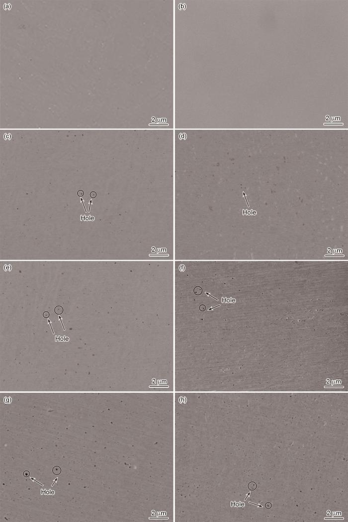
图2
辐照剂量不同的焊态和调质处理态焊缝表面的SEM照片
Fig.2
SEM morphological changes of two kinds of weld surfaces under different irradiation doses (a, c, e, g) 0, 5×10¹⁵, 5×10¹⁶, 1×10¹⁷ ions·cm-2 of as-welded welds; (b, d, f, h) 0, 5×10¹⁵, 5×10¹⁶, 1×10¹⁷ ions·cm-2 of quenched and tempered welds
2.2 微观组织观察
2.2.1 金相照片和TEM照片
图3给出了辐照前焊缝的试样的金相和TEM照片。由图3a可见,焊态焊缝的金相组织主要为板条马氏体和δ-Fe(图中箭头所示)。调质处理态焊缝的金相组织为晶粒细小、均匀分布的回火马氏体组织,其中δ-Fe已完全消除。图1c给出了焊态焊缝的TEM照片,可见平行排列的板条马氏体,尺寸为0.26~0.57 μm,马氏体内部为高密度缠结的位错亚结构,密度为0.6×1012 cm-2。调质处理后,组织变为板条特征更明显的回火马氏体,马氏体板条内部的位错因运动而大量湮灭,密度有所降低。同时,沿马氏体边界析出了棒状富Cr的M23C6型碳化物和细小圆球状富Ta的MC型碳化物[13],图1e,f为其TEM-EDX分析。
图3
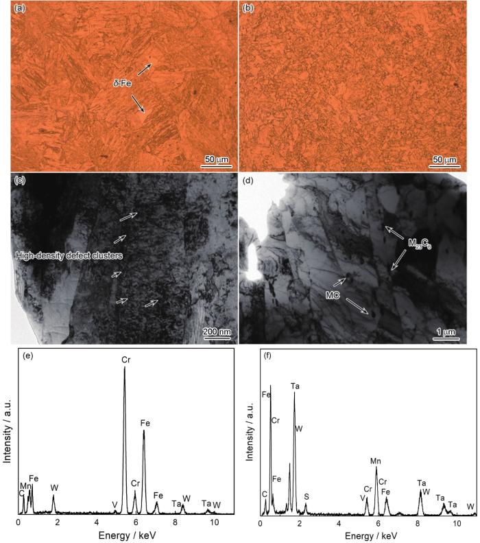
图3
辐照前焊缝的金相和TEM照片以及碳化物的TEM-EDX分析
Fig.3
Optical and TEM microstructure observation of welds and TEM-EDX analysis of carbides before irradiation (a, c) as-welded weld; (b, d) quenched and tempered weld; (e) Cr-rich M23C6 carbides; (f) Ta-rich MC particles
2.2.2 位错环
为了更好地了解辐照后材料中微观组织的演变,用TEM观察和分析最高剂量(1×10¹⁷ ions·cm-2)辐照后的试样。
辐照产生的空位和间隙原子等点缺陷聚集形成位错环[14],图4a,b给出了辐照后焊缝晶界处位错环的分布,右上角为其衍射花样标定。图4c,d为位错环的放大图和高分辨率图。根据不可见判据g·b=0,g=200时材料中产生b=<100>的位错环。为了更准确地计算位错环的尺寸和数密度,各选取三个图示大小相同的区域进行均值化统计,结果在图4e,f中给出。焊态焊缝中位错环的尺寸为18.97 nm、数密度为2.24×10²¹ m-3;调质处理态焊缝中位错环尺寸为15.73 nm,数密度为1.78×10²¹ m-3。界面作为缺陷阱捕获辐照点缺陷,降低了位错环的形核率[15,16]。焊缝经调质处理后,细小的晶界以及析出的碳化物和基体间的共界面都成为吸引辐照点缺陷的位点,从而降低了调质处理态焊缝中位错环的尺寸和数密度。
图4
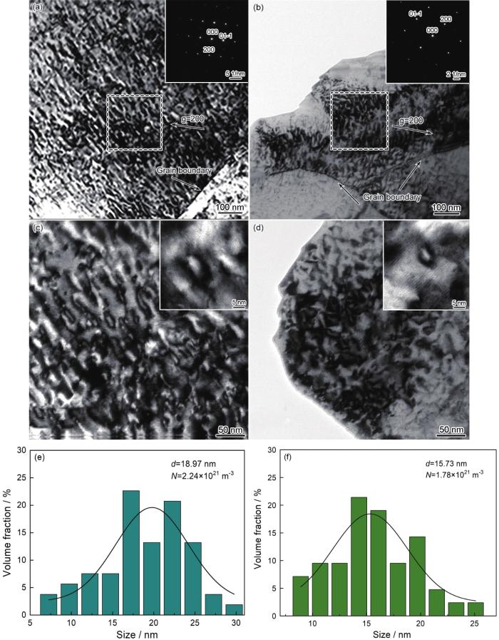
图4
辐照后焊缝中的位错环分布以及尺寸和数密度统计
Fig.4
Dislocation loops distribution and size and number density statistics of irradiated welds (a, c, e) as-welded welds; (b, d, f)quenched and tempered welds
2.2.3 氦泡
He在材料中的溶解度较低但是其扩散激活能也较低,当其浓度超过阈值时氦泡在晶界处形核并吸收He原子、空位和He-V复合体长大。对比图5a,b可见,焊态焊缝的晶界处生成了尺寸较大且密集的氦泡。为了更具体地了解氦泡的尺寸和数密度,各选取三个图示大小相同的区域进行均值化统计,结果在图5c,d中给出。可以看出,氦泡的尺寸分别为2.47 nm和1.70 nm,分布密度分别为2.7×10²³ m-3和2.1×10²³ m-3。位错环和氦泡相互作用,一方面位错环捕获He原子有利于氦泡聚集成泡,另一方面He团簇的尺寸和内压逐渐增大时为了保持材料内部的应变平衡,He团簇将临近的原子挤出而生成间隙型位错环,氦泡得以长大[17,18]。
图5
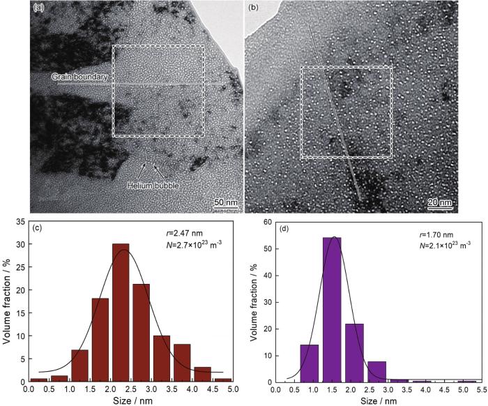
图5
辐照后焊缝中氦泡的分布以及尺寸和密度统计
Fig.5
Helium bubbles distribution and size and number density statistics of irradiated welds (a, c) as-welded welds;(b, d)quenched and tempered welds
氦泡增大材料的体积,导致辐照肿胀。利用统计出的氦泡的尺寸、数密度和试样厚度等参数,根据公式
可计算出材料的有效肿胀率S[19],式中∆V为氦泡的体积之和,V为氦泡统计区域的试样体积,r近似为球体半径。结果表明,焊缝的辐照肿胀率分别为1.7%和0.4%,调质处理态焊缝的辐照肿胀率比焊态焊缝的小,在一定程度上说明其抗辐照肿胀性能较好。
2.3 纳米硬度
图6
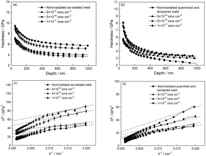
图6
辐照剂量不同的焊缝的纳米硬度与压入深度的关系
Fig.6
Nano-hardness vs. indentation depth after different implanted ion fluence (a, c) as-welded welds; (b, d) quenched and tempered welds
为了更准确地反映材料辐照层的硬度,采用Nix-Gao模型[21]
进行数据处理,结果在图6c,d中给出,曲线的纵坐标为H2,横坐标为1/h。式中H为所测纳米硬度值;H0 为材料辐照层的真实硬度;h*为材料的特征长度,与压头尺寸有关。根据曲线的截距可计算材料辐照层真实硬度值H0,结果列于表2。由图6c可见,焊态焊缝的曲线出现了一定转折。这表明,焊缝中有一个两种硬度相差较大的区域,即辐照损伤区和基体,此为软基体效应[22]。这个转折点的位置约在60 nm~100 nm处,其深度远小于SRIM模拟所得的辐照损伤层厚度(500 nm)。其原因是,压头压入材料产生的塑性变形区域约为压入深度的5~7倍[23],使理论计算出的转折点在70 nm~100 nm处,与实验结果相符。
表2 由Nix-Gao模型所得焊缝辐照层的真实硬度值H0
Table 2
| Fluence/ions·cm-2 | 0 | 5×10¹⁵ | 5×10¹⁶ | 1×10¹⁷ |
|---|---|---|---|---|
| 5.1 | 5.69 | 7.03 | 7.6 | |
| 3.54 | 3.76 | 4.26 | 4.6 |
由表2可见,焊态和调质处理态焊缝的辐照硬化率分别为49.0%和29.9%,利用Origin对纳米硬度值H0 与辐照损伤量(DPA)进行幂函数
拟合。式中a为拟合参数,表示同一辐照损伤量下,焊缝的硬化程度;b为拟合函数的幂指数。焊态焊缝中a≈7.36,b≈0.09,调质处理态焊缝中a≈4.46,b≈0.06,可见调质处理的焊缝其硬化程度较低,在一定程度上表明其抗离子辐照硬化性能更好。
图7
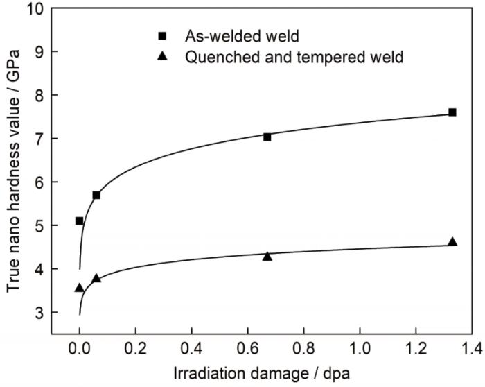
图7
焊态和调质处理态焊缝的纳米硬度与辐照损伤的关系
Fig.7
Relationship between nano-hardness value of as-welded and quenched and tempered welds and irradiation damage
3 结论
(1) 随着辐照剂量的增加CLAM钢焊缝表面黑色孔洞的尺寸增大、密度提高,调质处理态焊缝表面形成的黑色孔洞比焊态焊缝少。
(2) 与焊态焊缝相比,调质处理态焊缝经He+辐照形成的黑色孔洞和辐照点缺陷(位错环、氦泡)尺寸和数密度都较小,引起的辐照硬化较低,表明调质处理使焊缝的抗辐照性能提高。
参考文献
Fusion energy in context: Its Fitness for the long term
[J].
Irradiation hardening and defects distribution in CLAM steel under deuterium and helium ion irradiation
[J].
氘和氦离子辐照下CLAM钢的辐照硬化与微结构演变
[J].
Blanket/first wall challenges and required R&D on the pathway to DEMO
[J].
Surface and internal microstructure damage of He-ion-irradiated CLAM steel studied by cross-sectional transmission electron microscopy
[J].
In-situ observation of dislocation loop induced by electron irradiation on china low activation martensitic steel
[J].
中国低活化马氏体钢在电子辐照下产生位错环的原位观察
[J].
He and H irradiation effects on the nanoindentation hardness of CLAM steel
[J].
Effect of irradiation temperature on void swelling of China Low Activation Martensitic steel (CLAM)
[J].
Effect of heat treatment on microstructure and impact toughness of CLAM steel electron beam weld
[J].
热处理工艺对CLAM钢电子束焊缝显微组织与冲击韧性的影响
[J].
On the use of SRIM for computing radiation damage exposure
[J].
Measurement of hardness and elastic modulus by instrumented indentation: Advances in understanding and refinements to methodology
[J].
Effect of He+ fluence on surface morphology and ion-irradiation induced defect evolution in 7075 aluminum alloys
[J].
Rapid preparation and characterization of surface microstructures of AISI 304L austenitic stainless steel by high-current pulsed electron beam
[J].
AISI 304L奥氏体不锈钢表面微孔结构的强流脉冲电子束快速制备与表征
[J].
Microstructure and its influence on mechanical properties of CLAM steel
[J].
Chromium enrichment on the habit plane of dislocation loops in ion-irradiated high-purity Fe-Cr alloys
[J].
Study of defect evolution by TEM with in situ ion irradiation and coordinated modeling
[J].
In situ observation of damage structure in ODS austenitic steel during electron irradiation
[J].
Dual-beam irradiation of α-iron: Heterogeneous bubble formation on dislocation loops
[J].
The role of implanted gas and lateral stress in blister formation mechanisms
[J].
Induced swelling of ODS ferritic alloy MA957 tubing to 500 DPA
[J].
Helium ion irradiation induced swelling and hardening in commercial and experimental ODS steels
[J].
Indentation size effects in crystalline materials: A law for strain gradient plasticity
[J].
Application of small-scale testing for investigation of ion-beam-irradiated materials
[J].
A new approach to evaluate irradiation hardening of ion-irradiated ferritic alloys by nano-indentation techniques
[J].
