


M2高速钢(W6Mo5Cr4V2)是一种高碳、高合金莱氏体钢,具有较高的强度、韧性、良好的红硬性以及耐磨性,可用于制造各种刀具以及承受震动和高负载冲击的模具。M2高速钢含有W、Mo、V等强碳化物形成元素,因此含有大量的碳化物[1~3]。这些碳化物的种类、分布和尺寸等因素,对钢的力学性能如韧性、硬度以及耐磨性等有重要的影响[4,5]。卢林等[6]研究发现,较多的MC型碳化物会降低M3:2型高速钢的弯曲强度和冲击韧性。Rodenbury C[7]研究了碳化物尺寸分布对M3:2和M2高速钢干滑动摩擦的影响,发现钢中小尺寸碳化物的均匀分布能明显提高其耐磨性。俞峰等[8]研究发现,粗大角状碳化物降低钢的塑性和韧性、缩短刀具的使用寿命。
使用有原位加载台的扫描电子显微镜(SEM),可实时观察材料动态破坏中微裂纹的萌生、扩展直至最终断裂的整个过程。分析材料的组织形貌及第二相的尺寸、类型、数量对材料断裂的影响,有重要的学术价值[9,10]。Chen X等[11]用原位SEM技术研究了等温淬火硅合金钢的断裂行为,发现微裂纹主要在应力集中的析出相与基体之间的界面处形核。刘宝良[12]研究了D2模具钢的原位拉伸行为,发现:在变形过程中微裂纹多在碳化物与基体交界处形核,并向碳化物内部扩展。微裂纹扩展主要沿特定的解理面进行,随后相互连接成主裂纹。陈雷雷[13]在粉末冶金S390PM高速钢的原位拉伸实验中发现,MC型碳化物先断裂,而M6C型碳化物则不易断裂。本文原位SEM观察淬火-回火态M2高速钢形变过程中微裂纹的萌生和扩展,研究碳化物的种类、尺寸、形状以及分布等因素对M2高速钢力学性能的影响。
1 实验方法
实验用退火态M2高速钢棒材的直径为100 mm,其化学成分列于表1。将棒材切块,然后将试样加热到1200℃保温1 h后油淬,冷却至室温。再将试样在560℃高温回火三次,每次保温1 h。
表1 M2高速钢的化学成分
Table 1
| C | W | Mo | Cr | V | Si | Mn | P | S | Fe |
|---|---|---|---|---|---|---|---|---|---|
| 0.850 | 6.380 | 5.370 | 4.340 | 2.100 | 0.228 | 0.280 | 0.067 | 0.020 | Bal. |
将淬火-回火处理后的M2高速钢块加工成形状和尺寸如图1所示的试样,其厚度为1 mm。再将试样机械加工预制缺口,长度为1 mm。然后将试样的观察面细磨、抛光,并用4%硝酸酒精溶液腐蚀。
图1

用Apollo 300热场发射扫描电镜进行原位拉伸试验,手动加载。原位测试平台的拉伸速率为0.05 mm/min,每隔1 min停止加载进行拍照观察。在原位拉伸过程中载荷以及对应的位移数据由电脑自动保存。
用Zeiss Super-40热场发射扫描电子显微镜观察组织,使用扫描电镜配套的能谱(EDS)仪分析试样基体的组织和碳化物的元素含量。用JEM 2010F透射电镜(TEM)观察淬-回火试样的组织。
2 实验结果
2.1 淬火+回火后M2高速钢的显微组织
图2

图2
淬火+回火后M2高速钢的SEM照片和EDS分析
Fig.2
SEM images and EDS analysis of M2 high speed steel after quenching and tempering
图3

图3
M2高速钢淬火+回火后基体组织的TEM照片
Fig.3
TEM images of microstructure in M2 high speed steel after quenching and tempering (a) bright field image; (b) dark field image of martensite; (c) dark field image of austenite; (d) electron diffraction patterns
2.2 原位拉伸性能
图4

图4
M2高速钢的原位拉伸应力-应变曲线
Fig.4
Stress-strain curve of M2 high speed steel during in-situ tensile test
2.3 微裂纹的萌生和扩展
图5给出了M2高速钢原位拉伸过程中微裂纹的萌生和扩展。(1)在应力从0增加至180 MPa过程中,试样表面未出现明显的裂纹萌生,拉伸应力通过基体的弹性与塑性变形得到释放;(2)当应力达到180 MPa时大尺寸的条带状碳化物与基体塑性变形不协调,在界面处有微裂纹萌生,如图5a所示;(3)应力继续增大至442 MPa,从图5b可观察到,在基体上也有微裂纹萌生。同时,部分碳化物与基体界面分离后剥落形成孔洞,如图5c所示;(4)应力继续增大到646 MPa,基体上的裂纹数量和碳化物剥落形成的孔洞数量增加,碳化物与基体界面处的微裂纹扩展后连接成长裂纹甚至是网状裂纹(图5d)。还观察到部分大尺寸碳化物在应力的作用下断裂,如图5e所示。
图5

图5
在不同条件下微裂纹的萌生和扩展
Fig.5
Initiation and propagation of microcracks (a) σ=180 MPa; (b) (c) σ=442 MPa; (d) (e) σ=646 MPa
2.4 基体组织对微裂纹萌生-扩展的影响
上述结果表明,微裂纹可在碳化物/基体界面处和基体上萌生。为了研究基体组织对裂纹萌生与扩展的影响,进一步的观察拉伸结束后的试样。浮凸效应使回火马氏体与残余奥氏体的形貌明显不同。分别对图6中无裂纹区域以及有裂纹区域进行了EDS能谱分析,结果表明:与无裂纹区域(谱图2)相比,有裂纹区域(谱图1)的Fe含量低,而C、Cr、Mo、W等元素含量较多,与奥氏体的成分特征相符。使用纳米压痕仪分别对无裂纹区域和有裂纹区域进行纳米压痕测试,图7给出了载荷-位移曲线。测得无裂纹区域(区域2)的硬度和弹性模量值分别为4.15 GPa、384.8 GPa,有裂纹区域(区域1)的硬度和弹性模量值分别为2.02 GPa、186.8 GPa。有裂纹区域和无裂纹区域的纳米硬度与弹性模量,分别在文献[16]给出的奥氏体和马氏体的数值范围内。根据回火马氏体与残余奥氏体形貌、EDS能谱结果以及纳米压痕测试结果,确定有裂纹区域为残余奥氏体,无裂纹区域为回火马氏体。由此可见,与回火马氏体相比,裂纹更容易在残余奥氏体上产生。其原因是,残余奥氏体的强度低、塑性好,优先经历塑性变形,残余奥氏体塑性变形积累更早,当其塑性耗尽时裂纹便在残余奥氏体上萌生。
图6

图6
基体处萌生的微裂纹及其EDS分析
Fig.6
Microcracks initiated in the matrix and EDS analysis
图7

图7
有裂纹区(区域1)与无裂纹区(区域2)纳米压痕的载荷-位移曲线
Fig.7
Load-displacement curves for nano indentation of cracked area (region 1) and uncracked area (region 2)
2.5 碳化物对微裂纹萌生-扩展的影响
图8
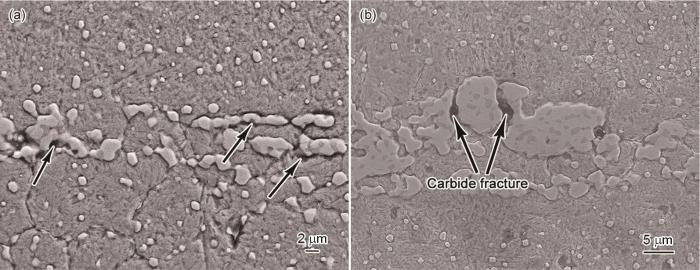
图8
碳化物引起的微裂纹的形貌
Fig.8
Morphology of microcracks induced by carbides (a) separation of carbides and matrix; (b) fracture of carbide
图9

图9
不同形状碳化物与基体界面处微裂纹的数量统计
Fig.9
Statistics of microcracks generated at the interfaces between matrix and carbides with different shapes (a) typical morphology of carbides with different shapes; (b) comparison of cracking rates
图10

图10
大尺寸碳化物的断裂形貌和EDS面扫描能谱
Fig.10
Fracture morphology and EDS area scanning of large-size carbide (a) morphology of cracked carbide; (b) schematic diagram of fractured carbide; (c) EDS analysis
3 讨论
其中E、υ分别为材料的弹性模量和泊松比。当σf 为碳化物与基体界面(p/m)的临界断裂应力σpm时,d为碳化物尺寸,γ为第二相/基体界面的相对表面能γpm;当σf 为基体(m)的临界断裂应力σm时,d为晶粒尺寸,γ为晶界的相对表面能γm。在淬火-回火态M2高速钢的组织中有些共晶碳化物很大,与晶粒尺寸相近,而γpm、γm分别约为9 J/m2、52 J/m2[17]。由
其中γ为碳化物的表面能。由
4 结论
(1) 在M2高速钢原位拉伸过程中,微裂纹在大尺寸共晶碳化物与基体界面处和残余奥氏体上萌生与扩展,以前者为主;部分碳化物与基体界面分离后剥落,产生孔洞。随着应力的增大碳化物与基体界面处的微裂纹扩展后连接成网状裂纹,大尺寸碳化物断裂。
(2) 与回火马氏体相比,裂纹更容易在残余奥氏体上萌生。碳化物的尺寸、形状以及种类,对微裂纹的萌生和扩展也有重要的影响。与小尺寸碳化物相比,大尺寸碳化物与基体的界面更容易产生微裂纹,其自身也容易断裂;不规则形状碳化物/基体界面处更易萌生微裂纹,MC型碳化物比M6C型更容易开裂。
(3) 减少块状残余奥氏体、一次共晶碳化物和MC碳化物的数量、减小碳化物的尺寸和改善碳化物形状,都能减缓微裂纹的萌生和扩展。
参考文献
Solidification of High Speed Steels
[J].
Effects of alloying elements on microstructure and fracture properties of cast high speed steel rolls: Part I: Microstructural analysis
[J].
Effect of solidification rate on the morphology and distribution of eutectic carbides in centrifugal casting high-speed steel rolls
[J].
Relations between fracture toughness, hardness and microstructure of vacuum heat-treated high-speed steel
[J].
Effect of heat and cryogenic treatment on wear and toughness of HSS AISI M2
[J].
Effect of niobium on the microstructure and properties of spray-formed M3:2 high speed steel
[J].
铌对喷射成形M3:2型高速钢组织和性能的影响
[J].
A quantitative analysis of the influence of carbides size distributions on wear behaviour of high-speed steel in dry rolling/sliding contact
[J].
Carbide defect in high speed steel
[J].
高速钢中的碳化物缺陷
[J].
In situ scanning electron microscopy
[J].
Recent advances on in situ sem mechanical and electrical characterization of low-dimensional nanomaterials
[J].
In-situ SEM observation on fracture behavior of austempered silicon alloyed steel
[J].
The in-situ study on the coordinate rotation of metal micro structure in plastic deformation
[D].
金属变形过程中微观组织协调行为的原位研究
[D].
Study on alloy carbides control in high speed steel
[D].
高速钢合金碳化物控制研究
[D].
Phase transformation refinement of coarse primary carbides in M2 high speed steel
[J].
Influence of rare earths on eutectic carbides in AISI M2 high speed steel
[J].
The energy absorption effect and microstructure evolution of high-speed steels under high pressure
[D].
高应力作用下高速钢能量吸收效应及组织演变
[D].
Cleavage initiation in steel: Competition between large grains and large particles
[J].
The role of grain size in brittle particle induced fracture of steels
[J].
Fracture toughness of carbides in tool steels evaluated by nanoindentation
[J].
Deformation-induced carbide transformation in M2 high-speed steel
[J].
Effect of alloying elements and homogenization treatment on carbide formation behavior in M2 high speed steels
[J].
