


DLC薄膜由金刚石相的sp3和石墨相的sp2杂化碳键组成,具有高硬度、良好耐磨性、化学惰性和光学特性等优异性能[4]。PEEK材料与DLC薄膜复合,可互补两者的性能优势并拓宽其应用领域。但是,DLC薄膜的内应力较高且其力学、热膨胀系数等物化性能与PEEK的差别较大。这使两者的界面结合力较弱、协同形变能力差,使薄膜易剥落、抗弯压疲劳能力差[5,6]。DLC薄膜的厚度、界面结构和化学键态,是影响两者粘结强度的关键因素。改变沉积时间,可调控薄膜的厚度和界面状态 [7]。同时,柔性基材改性后的表面结构和性能,也随等离子体刻蚀或DLC薄膜的沉积时间而变化[8,9]。本文采用直流磁控溅射技术,以石墨为阴极靶材,改变沉积时间在PEEK表面制备不同厚度的DLC薄膜,研究沉积时间对PEEK/DLC复合材料的表/界面结构、组分,以及疏水、力学和光透过性能的影响。
1 实验方法
1.1 DLC薄膜的制备
使用直流磁控溅射(Direct current magnetron spu-ttering,DCMS)设备在PEEK表面沉积DLC薄膜。以99.999%石墨为阴极靶材,使用高纯Ar为工作气体,基体为PEEK(厚度0.1 mm)。沉积薄膜前,先使用乙醇对PEEK基体超声清洗15 min,其表面风干后置于腔内旋转基架上并关闭腔室。在实验过程中,使用20℃的循环冷却水使腔体降温。将腔体真空抽至2.7×10⁻³ Pa,设置基体偏压为-450 V(350 kHz,1.1 μs),工作气压为1.06 Pa,用Ar+刻蚀清洗PEEK基体表面20 min,腔体的温度为20~29℃。沉积DLC薄膜时将基架转向正对靶材位置,设置靶材与基体距离为10 cm,基架自转速度为6 r/min。通入75 mL/min的Ar气体并打开磁控溅射电源,设置溅射电流为3.0 A(功率2.1 kW),基体脉冲偏压为-200 V(350 kHz,1.1 μs)。DLC薄膜沉积系统的示意图,如图1所示。在沉积过程中腔体的温度为29~47℃,压力为0.30 Pa,沉积时间分别为2、8、15、20、32和40 min。
图1
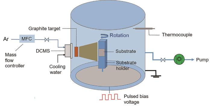
图1
DLC薄膜沉积系统的示意图
Fig.1
Schematic diagram of the deposition system for DLC films
1.2 薄膜的表征
使用Hitachi S-4800型的场发射扫描电镜(SEM)和FEI Tecnai F20型的高分辨透射电镜(HRTEM)表征薄膜表面和横截面微观形貌。用聚焦离子束(FIB)方法制备HRTEM样品。用X切割法评估PEEK与DLC薄膜的界面结合强度:用刀片将样品表面的DLC薄膜切成X型,交叉线的角度为30°~45°。在10 N恒压条件下将3 M胶带(粘附力为47 N/100 mm)粘结在薄膜表面并在2 min后将胶带沿180°撕开,用SEM观察X切割区域处表面DLC薄膜的裂纹和剥离程度[10]。使用Renishaw inVia Reflex拉曼(Raman)谱仪表征薄膜碳原子键结构。使用Axis Ultradld型X射线光电子能谱仪(XPS)检测薄膜表面化学成分和元素结合状态。使用Dimension 3100V型扫描探针显微镜中的原子力显微镜(AFM)模块测试薄膜表面的粗糙度。用OCA 20接触角测量仪测试薄膜表面疏水性。用MTS-G200型的纳米压痕仪测试PEEK/DLC复合薄膜硬度和弹性模量。用Lambda 950型紫外/可见/近红外分光光度计测试PEEK/DLC复合薄膜的光透过率。
2 结果和讨论
2.1 DLC薄膜表/界面形貌
图2

图2
不同沉积时间PEEK/DLC复合薄膜表面的SEM照片
Fig.2
Surface SEM images of PEEK/DLC composite films with different time (a, b) 2 min, (c, d) 8 min, (e, f) 15 min, (g, h) 20 min, (i, j) 32 min, (k, l) 40 min
图3给出了不同沉积时间PEEK/DLC复合薄膜横截面的HRTEM照片。图3g给出了沉积DLC薄膜的HRTEM放大图,沉积时间为2~40 min的DLC薄膜均有与此相同的结构。从选区电子衍射图可见,沉积的薄膜具有典型的非晶结构。沉积时间为2~20 min的DLC薄膜较薄,PEEK基体的影响和碳粒子刻蚀较为明显,使复合薄膜表面的弯曲度较大。碳粒子的刻蚀使DLC薄膜与PEEK界面逐渐形成了锯齿或凹凸状的机械咬合结构,增大了接触面积而使结合强度提高。沉积时间由20 min增至40 min时,由于DLC薄膜较厚,PEEK基体的柔性影响和碳粒子刻蚀均减弱,使复合薄膜表面的弯曲度减少,但是界面处的咬合结构仍有一定程度的提高,有利于增大膜/基附着力[13]。这些结果表明,碳粒子对基体表面的刻蚀程度随沉积时间的延长而提高,而沉积出的DLC薄膜在碳粒子轰击过程中保护了基体[14]。
图3
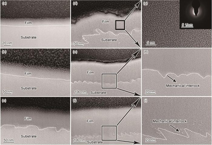
图3
不同沉积时间PEEK/DLC复合薄膜横截面的HRTEM照片
Fig.3
Cross-section HRTEM images of PEEK/DLC composite films with different time (a) 2 min, (b) 8 min, (c) 15 min, (d) 20 min, (e) 32 min, (f) 40 min, (g) enlarged image of DLC films, (h, i) interface structures of 32 and 40 min
PEEK基体与DLC薄膜物化性能的巨大差异,使沉积过程中表面出现变形。用表面轮廓仪测量的厚度值误差较大,因此参考文献[10]中的方法测量HRTEM图中DLC薄膜的横截面长度。薄膜厚度和平均沉积速率随时间的变化曲线,在图4中给出。可以看出,沉积时间由2 min增加到40 min,DLC薄膜的厚度由11.26 nm增大至230.93 nm。平均沉积速率维持在5.63~5.77 nm/min范围内[15],用线性拟合得到的平均沉积速率值为5.71 nm/min。在DLC薄膜的沉积过程中,溅射粒子中的部分中性原子或分子沉积在PEEK基体上生成薄膜,溅射粒子中的离子则在负偏压作用下吸引到基体表面参与成膜。偏压的大小,影响离子到达基体的数量和能量[16]。另一方面,粒子对基体和已沉积薄膜的轰击,使薄膜中结合较弱的碳原子被反溅射离开薄膜表面。在沉积过程中这两方面的综合作用达到动态平衡,使DLC薄膜的沉积速率保持在5.71 nm/min。
图4
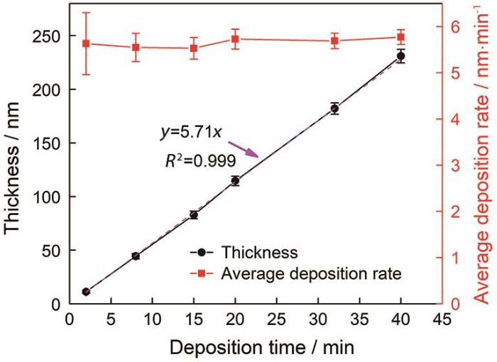
图4
PEEK表面DLC薄膜的厚度和平均沉积速率与沉积时间的关系
Fig.4
Curves of the thickness and the average deposition rate of DLC films on PEEK over time
2.2 PEEK基体与DLC薄膜的结合强度
用X切割法测试了不同沉积时间PEEK/DLC复合薄膜的粘结力,结果如图5所示。可以看出,沉积时间为0~40 min,DLC薄膜与PEEK间的粘结力较大。从X切割区域的SEM放大图,可对比不同沉积时间DLC薄膜与PEEK间的粘结力。对于柔性PEEK/DLC复合材料,X切割引起的拉伸应力可通过垂直于拉伸方向的裂纹及DLC薄膜在基体表面的剥落释放。如果粘附力足够大,裂纹的产生和张开是释放应力的唯一途径,可观察到高密度裂纹;如果粘附力较小,除了裂纹,裂纹的脱粘也会使应力释放[17]。因此,DLC薄膜裂纹的尺寸越小或剥落越少,表明附着力越大[18]。可以看出,随着沉积时间的延长DLC薄膜的厚度逐渐增大,使残余应力较大,其剥落现象也逐渐明显,附着力逐渐减小,X切割区域处的裂纹均呈长条状。这些裂纹尺寸逐渐增大,在DLC薄膜覆盖区域应力集中而形成小凸起。沉积2 min的DLC薄膜较薄,其硬度和弹性模量与PEEK基体相差较小,协同形变能力大,粘附力较大。虽然使粘附力增大的界面互锁结构随时间逐渐加强(图3),但是DLC薄膜厚度的影响起主导作用,使界面的结合强度随着沉积时间的延长而降低。
图5
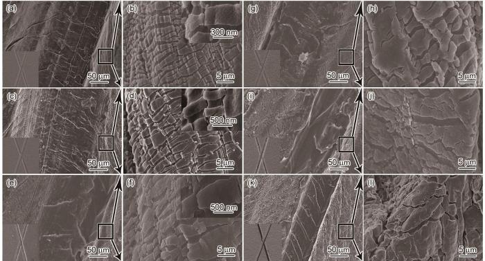
图5
不同沉积时间PEEK/DLC复合薄膜的粘结力
Fig.5
SEM images of PEEK/DLC composite films with different time (a, b) 2 min, (c, d) 8 min, (e, f) 15 min, (g, h) 20 min, (i, j) 32 min, (k, l) 40 min
2.3 DLC薄膜的Raman谱
为了消除基体的荧光影响并减少Raman测试对样品的损伤,选用325 nm紫外波长和0.5 mW激光能量Raman表征PEEK/DLC复合薄膜,结果如图6所示。可以看出,沉积时间由2 min增至40 min在1100~1800 cm-1复合薄膜表面的特征峰(D峰和G峰)均较明显。随着沉积时间的延长腔体的温度缓慢升高,ID/IG值逐渐增大。随着沉积时间由2 min延长至15 min,ID/IG值由0.23缓慢增至0.25,sp3的含量较高。PEEK高分子材料分子结构中含有苯环等碳键结构(图6b),使其在1000~1700 cm-1范围内存在碳碳伸缩、碳氢摇摆及其耦合振动,在Raman谱图中出现显著的D峰和G峰[21]。沉积时间≤15 min的DLC薄膜较薄(膜厚≤82.94 nm),Raman表征时易检测到PEEK基体表面,使拟合出的G峰面积值偏大,ID/IG值较小。而沉积时间>15 min(20~40 min)时沉积的DLC薄膜较厚,基体影响较弱,测得碳膜的本征Raman谱图,G峰面积值大幅减小,使得ID/IG值突增至0.81,并继续缓慢增至0.84(图6b),sp2/sp3值较大,表明膜内的有序度提高。
图6
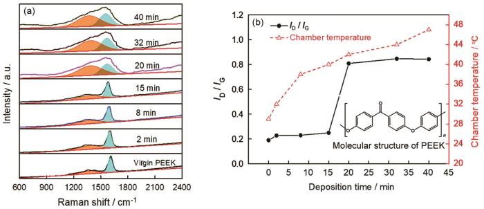
图6
不同沉积时间PEEK/DLC复合薄膜的Raman谱、ID/IG值、腔体温度以及PEEK的分子结构式
Fig.6
Raman spectra (a), ID/IG ratio of PEEK/DLC composite films, chamber temperature with different time and the molecular structure of PEEK (b)
2.4 DLC薄膜表面的化学状态
为了分析薄膜表面化学键状态,对样品进行了XPS表征,结果如图7所示。由图7a可以看出,纯PEEK和不同沉积时间的PEEK/DLC复合薄膜的O 1s谱图均可拟合分成两个峰:531.86 eV(C=O)和533.44 eV(C-O)[22]。图7c给出了PEEK/DLC复合薄膜表面碳氧原子比(C/O)、C和O元素及C-O键、C=O键相对浓度随时间的变化规律。其中C/O比可通过XPS全谱分析C和O元素峰积分强度计算。沉积时间延长至15 min的DLC薄膜,其中C的相对含量逐渐提高而O含量降低。沉积时间延长到20~40 min,薄膜中的C和O含量基本上不变。纯PEEK的C=O和C-O组分的相对浓度分别为31.21%和68.79%,比值约为0.45,与根据PEEK分子结构式中重复单元计算的理论值(0.5)相接近。不同沉积时间的PEEK/DLC,与纯PEEK表面O键含量差异较大。沉积2 min的薄膜,C=O键相对浓度降低至18.70%,而C-O键的相对浓度提高到81.30%。PEEK/DLC复合薄膜中C-O键相对浓度随沉积时间的延长先升高后趋于平缓,而C=O键的相对浓度先降低后趋于平缓。其原因是,在沉积初期,PEEK表面入射碳粒子轰击时的高能量使PEEK表面部分碳化以及碳粒子的沉积,生成了更多的C-C键,部分C=O键转化为C-O键,结果是O元素和C=O键的含量逐渐降低。
图7

图7
不同沉积时间PEEK/DLC复合薄膜表面的O 1s谱图、C 1s谱图、C元素、O元素、C-O键和C=O键的相对浓度以及C/O比、sp2和sp3含量和sp2/sp3值
Fig.7
O 1s (a) and C 1s spectra (b), the content of C element, O element, C-O bond and C=O bond, and the ratio of C/O (c), the content of sp2 and sp3, the ratio of sp2/sp3 (d) for the surface of PEEK/DLC composite films with different time analyzed
如图7b所示,纯PEEK的C 1s谱可分解为:284.94 eV(C-C/C-H)、285.89 eV(C-O)和288.82 eV(C=O),含量分别为71.08%、23.90%、5.02%,与理论值(74.1%、20.7%、5.1%)吻合[22,23]。而PEEK/DLC的C 1s谱图可分解为:284.55 eV(C sp2杂化键),285.34 eV(C sp3杂化键)和288.18 eV(C=O),其中sp2碳键和sp3碳键的比值可由两者峰面积比得出,计算结果如图7d所示。结果表明,随着沉积时间的延长sp2含量逐渐提高,sp2/sp3值由0.58逐渐增大至1.12并趋于平缓。由于在沉积初期碳粒子注入过程中产生了压应力,易形成sp3键,使sp2/sp3值较小。随着DLC薄膜厚度的增大碳粒子的注入将离子动能转化为热能,使已沉积的DLC薄膜和PEEK基体的温度升高[24]。这一方面使DLC薄膜内部的压应力部分释放,不利于sp3键的形成;另一方面使已形成的部分sp3键又转变为sp2键,sp2团簇界域扩大,部分C=C键向C原子环形式转化,使薄膜的石墨化程度提高[25]。基体升温的影响超过了碳粒子注入对形成sp3键的促进作用,使薄膜中sp3键的含量逐渐降低[26,27]。
2.5 DLC薄膜表面的粗糙度和润湿性
由于PEEK基体较软,碳粒子在沉积过程中对基体进行轰击刻蚀同时在基体表面沉积生成DLC薄膜。碳粒子刻蚀一方面导致PEEK基体表面产生一定破坏(氧化、碳化或分解),另一方面因DLC薄膜与PEEK弹性模量相差较大使PEEK表面产生残余应力,并通过产生凹陷或凸起方式释放,进而形成纳米尺寸的褶皱图案[28]。
图8和图9分别给出了不同沉积时间PEEK/DLC复合薄膜表面粗糙度(Ra)、水接触角随时间的变化以及表面三维高度图。可以看出,纯PEEK表面有一定的粗糙度,Ra值约217 nm。随着沉积时间的延长PEEK/DLC表面Ra和水接触角均呈先增大后减小的趋势。沉积时间为32 min时,表面Ra和水接触角均分别达到最大值495 nm和108.29°。沉积时间由2 min增至32 min,一方面,碳粒子的刻蚀使薄膜表面的褶皱结构增多(图9);另一方面,DLC薄膜优先在凸起部位生长[29,30],使固-液接触时捕获大量空气,有利于薄膜表面粗糙度和疏水性的提高[31,32]。另外,PEEK表面C-C键的形成、O含量的降低以及sp2/sp3值增大,也使薄膜表面疏水性提高[33]。其原因是,本征石墨表面悬挂键较少,sp2含量高,具有较低的表面自由能和更好的疏水性,说明富sp2表面与富sp3表面相比有更大的接触角。而随着沉积时间延长到40 min,沉积的DLC薄膜增厚(278.89 nm)减弱了碳粒子对基体的刻蚀并对薄膜表面凹状结构进行了部分覆盖或填充,产生的平滑作用使表面粗糙度略有降低,水滴较易穿过空气间隙而使接触角减小[34,35]。
图8
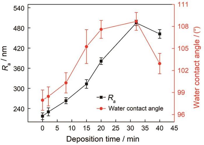
图8
PEEK/DLC复合薄膜表面的粗糙度(Ra)和水接触角与沉积时间的关系
Fig.8
Curves of the surface roughness (Ra) and water contact angles for PEEK/DLC composite films over time
图9
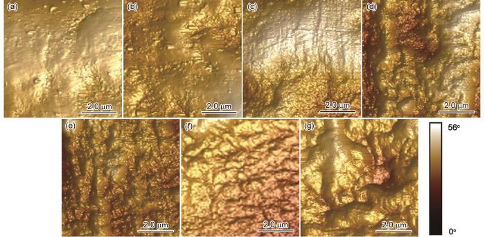
图9
不同沉积时间PEEK/DLC表面的三维高度图
Fig.9
Surface three dimensional height images of PEEK/DLC at different time (a) virgin PEEK, (b) 2 min, (c) 8 min, (d) 15 min, (e) 20 min, (f) 32 min, (g) 40 min
2.6 PEEK/DLC复合薄膜的力学和光透过性能
纳米压痕测试柔性PEEK基体时,压头的尖端与基体的接触属于粘弹性接触,压痕卸载发生的蠕变使杨氏硬度的测量值偏大[36,37]。因此,在测试过程中将压头在最大载荷下保持一段时间以避免PEEK粘弹性的影响[38]。因为PEEK基体的厚度只有0.1 mm,与硬质基体(Si片、不锈钢片)相比较软,且在沉积时间为2~15 min的DLC薄膜较薄,直接测试PEEK表面DLC薄膜的力学性能难以实现。因此,尝试测定整个PEEK/DLC复合薄膜的硬度(H)和弹性模量(E)[39]。采用深度(位移)控制模式下恒定应变速率加载压痕测量PEEK粘弹性材料,实验参数为:最大压入深度100 nm,位移速度5 nm/s,保载时间10 s,应变速率0.05 1/s,采集频率45 Hz,卸载速率0.002 mN/s。根据载荷、H和E与深度的变化曲线得到的不同沉积时间样品的H和E值,如图10所示。可以看出,对于PEEK/DLC软硬复合薄膜,随着DLC薄膜硬质相厚度的增加复合薄膜的硬度和弹性模量均逐渐增大。在沉积初期,沉积时间为2~15 min的DLC薄膜较薄(11.26~82.94 nm),PEEK基体对复合薄膜的力学性能影响起主导作用,DLC薄膜硬质相的作用较弱,使复合薄膜的硬度和弹性模量的提高都不明显。沉积时间为20~40 min的DLC薄膜厚度为114.55~230.93 nm,DLC薄膜硬质相的影响增大,使复合薄膜的硬度和弹性模量明显提高。随着DLC薄膜厚度的增大,复合薄膜的硬度和弹性模量分别由0.256 GPa和2.84 GPa显著提升至3.50 GPa(约14倍)和21.80 GPa(约7.7倍)。
图10
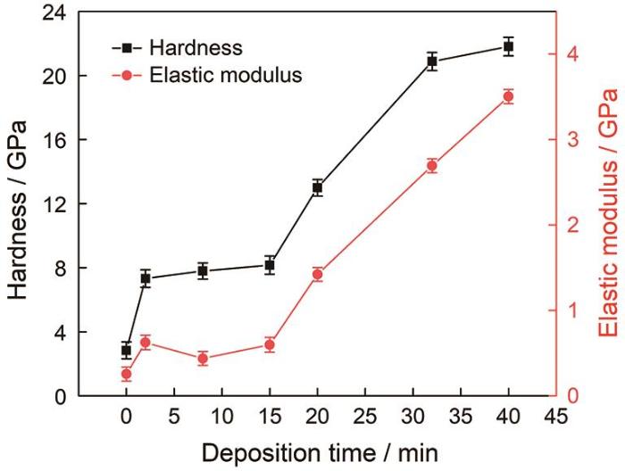
图10
PEEK/DLC复合薄膜硬度和弹性模量与沉积时间的关系
Fig.10
Curves of the hardness and elastic modulus for PEEK/DLC composite films over time
另外,对样品在紫外/可见/近红外范围(0~2500 cm-1)内的光透过率的表征结果如图11所示。可以看出,随着沉积时间的延长,PEEK/DLC复合薄膜的紫外线和近红外线透过率都逐渐降低。沉积时间≥8 min(膜厚62.39 nm)的复合薄膜其紫外透过率<5%,红外线透过率<40%,表明其具有优异的抗紫外线老化及阻隔红外线性能。
图11

图11
不同沉积时间PEEK/DLC复合薄膜的光透过率曲线
Fig.11
Transmission curves of PEEK / DLC composition films prepared at different time (a) and enlarged image of part A (b)
3 结论
(1) 采用直流磁控溅射技术通过改变沉积时间可在厚度为0.1 mm的PEEK表面制备厚度为11.26~230.93 nm的DLC薄膜。随着沉积时间的延长DLC薄膜厚度线性地增大,碳原子致密性也逐渐提高。
(2) 碳粒子的轰击刻蚀使PEEK与DLC薄膜间的机械互锁结构逐渐增强。DLC薄膜厚度的影响大于界面互锁结构的作用,使界面的结合强度随着沉积时间的延长而降低。
(3) 沉积时间≤15 min时,基体结构的影响使sp2/sp3比值较小(0.58~0.74),ID/IG值为0.23~0.25;时间>15 min时,基体影响较弱使ID/IG值突增至0.81,sp2/sp3值也比较大(0.96~1.12)。
(4) 在沉积过程中碳粒子的注入将离子动能转化为热能,导致PEEK基体温度升高,使DLC薄膜ID/IG值增大、sp2含量和薄膜的石墨化程度提高,使薄膜表面的O含量降低后趋于平缓,部分C=O键转化为C-O键。
(5) 随着沉积时间的延长,PEEK/DLC复合薄膜的硬度和弹性模量、防紫外线和阻隔红外线性能提高、表面纳米褶皱结构增多、表面粗糙度和疏水性先升高后降低。沉积时间为32 min时表面水接触角和粗糙度达到最大值,分别为108.29°和495 nm。
参考文献
A combination of CO2 laser and plasma surface modification of poly(etheretherketone) to enhance osteoblast response
[J].
Effect of laser groove treatment on shear bond strength of resin-based luting agent to polyetheretherketone (PEEK)
[J].
The mechanical properties of polyetheretherketone (PEEK) are ideally suited for fixed dental prostheses. However, PEEK typically has low adhesion strength to resin-based luting agent. This study assessed the shear bond strength between laser groove treated PEEK and resin-based luting agent.A total of 230 specimens were randomly divided into five groups (n=46): no-treatment, air abrasion treatment, 100μm-deep, 150μm-deep, and 200μm-deep laser groove treatments. The surface roughness was measured, scanning electron microscopy was used to observe the specimen surfaces, and X-ray photoelectron spectroscopy (XPS) was used to analyze the surfaces. Each group was divided into four resin-based luting agent subgroups: Panavia V5, RelyX Ultimate Resin Cement, G-CEM Link Force, and Super-Bond C&B. After the resin-based luting agent was bonded to the specimens, the bond strength was measured using shear tests and the failure modes were assessed by stereomicroscopy. The surfaces were also observed by scanning electron microscopy (SEM) after the shear bond strength measurements. The data were statistically analyzed using a two-way analysis of variance and Tukey's honest significant difference test (α=0.05).The PEEK surface after laser groove treatment groups exhibited the highest mean Ra values. In the XPS analysis, the laser treated PEEK surface exhibited an effective surface composition for bonding with resin-based luting agent. The shear bond strengths for the laser groove treated samples were significantly higher (p<0.05) than those of the no-treatment and air abrasion treatment groups.The shear bond strength between PEEK and resin-based luting agent was substantially improved by laser groove treatment.Copyright © 2018 Japan Prosthodontic Society. Published by Elsevier Ltd. All rights reserved.
Effect of metal doping on structural characteristics of amorphous carbon system: a first-principles study
[J].
Structure and mechanical properties of W incorporated diamond-like carbon films prepared by a hybrid ion beam deposition technique
[J].
Fabrication of diamond-like carbon film on rubber by T-shape filtered-arc-deposition under the influence of various ambient gases
[J].
Residual compressive stress enabled 2D-to-3D junction transformation in amorphous carbon films for stretchable strain sensors
[J].
Evolution of optical properties with deposition time of silicon nitride and diamond-like carbon films deposited by radio-frequency plasma-enhanced chemical vapor deposition method
[J].
Diamond-like carbon films for PET bottles and medical applications
[J].
On the deposition and properties of DLC protective coatings on elastomers: a critical review
[J].
Microstructure, adhesion and tribological behaviors of Si interlayer/Si doping diamond-like carbon film developed on nitrile butadiene rubber
[J].
Effects of bias voltage on the microstructure and properties of Al-doped hydrogenated amorphous carbon films synthesized by a hybrid deposition technique
[J].
Resonant Raman spectroscopy of disordered, amorphous, and diamondlike carbon
[J].
Highly adhesive and high fatigue-resistant copper/PET flexible electronic substrates
[J].
Microstructural and frictional control of diamond-like carbon films deposited on acrylic rubber by plasma assisted chemical vapor deposition
[J].
Deposition of diamond-like carbon films on insulating substrates by plasma source ion implantation
[J].
Impact of bias on the graphite-like carbon films grown by high power impulse magnetron sputtering
[J].
基体偏压对高功率脉冲磁控溅射制备类石墨碳膜的影响研究
[J].
Tribological performance of DLC films deposited on ACM rubber by PACVD
[J].
Improvement of thermal stability, adhesion strength and corrosion performance of diamond-like carbon films with titanium doping
[J].
Interpretation of Raman spectra of disordered and amorphous carbon
[J].
A phenomenological approach for the Id/Ig ratio and sp3 fraction of magnetron sputtered a-C films
[J].
Identification of the characteristic vibrations for 16 PAHs based on Raman spectrum
[J].
拉曼光谱的16种多环芳烃(PAHs)特征振动光谱辨识
[J].
Polyetheretherketone (PEEK) surface functionalization by low-energy ion-beam irradiation under a reactive O2 environment and its effect on the PEEK/Copper adhesives
[J].
Photofunctionalization effect and biological ageing of PEEK, TiO2 and ZrO2 abutments material
[J].
Substrate tilting effect on structure of tetrahedral amorphous carbon films by Raman spectroscopy
[J].
Thickness dependent electronic structure of ultra-thin tetrahedral amorphous carbon (ta-C) films
[J].
Effects of deposition temperature on the properties of hydrogenated tetrahedral amorphous carbon
[J].
Improved adaptability of PEEK by Nb doped graphite-like carbon composite coatings for bio-tribological applications
[J].
Diamond-like-carbon film prepared on stainless steel substrates by liquid phase electrochemical deposition
[J].
不锈钢上液相电沉积类金刚石薄膜
[J].以甲醇有机溶液作碳源,应用直流脉冲电化学沉积方法,在不锈钢表面制备了类金刚石碳薄膜.用原子力显微镜、扫描电镜、拉曼光谱仪和傅立叶红外吸收光谱表征该薄膜的表面形貌和结构.结果表明:经电化学沉积的含氢类金刚石碳薄膜均匀、致密,表面粗糙度小;Raman光谱在1 332.51cm-1处有一强的谱峰,与金刚石的特征谱峰相重合.加入活性添加剂,增加了电流密度,使沉积速率提高到0.5μm/h.
Water condensation behavior on the surface of a network of superhydrophobic carbon fibers with high-aspect-ratio nanostructures
[J].
Extreme water repellency of nanostructured low-surface-energy non-woven fabrics
[J].
Water condensation behavior on the surface of a network of superhydrophobic carbon fibers with high-aspect-ratio nanostructures
[J].
Correlations between microstructure and hydrophobicity properties of pulsed laser deposited diamond-like carbon films
[J].
Wettability of porous surfaces
[J].
Nanoscale patterning of microtextured surfaces to control superhydrophobic robustness
[J].
Analysis of nanoindentation creep for polymeric materials
[J].
Load-displacement relations for nanoindentation of viscoelastic materials
[J].
Nano-indentation of polymeric surfaces
[J].
