
文献标识码: 分类号 TG174.4 文章编号 1005-3093(2016)08-0614-07
收稿日期: 2016-01-20
网络出版日期: 2016-09-28
版权声明: 2016 《材料研究学报》编辑部 《材料研究学报》编辑部
基金资助:
展开
摘要
采用电弧离子镀技术在不锈钢基体上制备了大厚度TiAlN涂层, 并对大厚度涂层的力学性能进行了系统的研究。结果表明: 梯度增加和循环增加N2流量制备大厚度涂层的厚度分别达到68.79 µm和64.48 µm, 且涂层力学性能良好; 大厚度涂层残余应力沿层深的分布, 总体趋势从膜基界面向表面逐渐增大, 全膜厚平均压应力低于1 GPa, 表面硬度近2000 HV, 循环大厚度涂层的膜基结合好于梯度大厚度涂层, 而梯度大厚度涂层展现出更低的摩擦系数与磨损率。
关键词:
Abstract
The mechanical property of TiAlN coatings of large thickness deposited on stainless steel substrate by arc ion plating (AIP) was systematically investigated. The results indicated that the thickness of the coatings deposited by AIP with the increasing flow of N2 by way of cycle or stepwise could reach 68.79 µm and 64.48 µm respectively, and those coatings show fairly well mechanical performance. The depth profile of residual stress of the coatings presented a general trend that the stress increased gradually from the coating/substrate interface to the top surface. The average compressive stress of the coatings is lower than 1 GPa, and its surface hardness almost reaches 2000 HV. The former coating has lower friction coefficient and wear rate, whereas the later one shows better coating/substrate adhesion.
Keywords:
TiN涂层具有较高的硬度和较低的摩擦系数以及良好的化学稳定性等优良性能, 在工业中有着广泛的使用[1-4]。Ti A1N等三元涂层是在TiN的基础上发展起来, 不仅保持了TiN涂层的高硬度和低摩擦系数等优点, 还表现出更好的高温抗氧化性[5-8]和高温耐磨性能[9-11]。
物理气相沉积(PVD)是当前制备TiAlN等硬质薄膜的主要技术, 这种技术得到的硬质膜的残余应力一般是压应力, 而且数值往往很大, 甚至高达-17 GPa[12, 13]。过大的残余压应力可使薄膜从基片上脱落, 或使其翘曲、鼓包。现已提出多种方法来抑制过高的残余压应力, 其中包括改进沉积工艺[14]、制备多层膜[15, 16]、采用成分梯度[17-19]、引入过渡层[20-22]、以及沉积后进行退火处理[23]等。尽管这些方法有效改善了涂层残余应力, 提高了膜基结合力, 但当涂层厚度增大时, 即使涂层平均应力没有增大, 膜基界面剪切力(涂层截面积×涂层平均应力)也会显著上升, 使得大厚度硬质涂层难以制备。这使得广泛应用的普通硬质涂层厚度, 一直在3~5 μm左右。在保持硬质涂层的力学性能(硬度和膜基结合力)的前提下, 增加其厚度, 必然大幅度提高其使用寿命。
在前期工作中, 我们通过调节工艺成功制备了厚度达130 μm的TiAlN硬质涂层[17], 但并未对其力学性能进行深入分析研究。本工作采用电弧离子镀技术, 进一步优化工艺, 镀膜过程中分别通过循环和梯度改变氮流量, 在不锈钢基体上分别制备了两种大厚度TiAlN涂层, 并对其截面形貌、成分分布、硬度、膜基结合力、残余应力及摩擦磨损等进行了系统的分析研究。
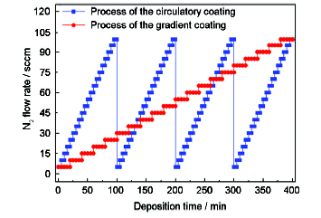
选用316L不锈钢作为基底材料, 其弹性模量E和泊松比υ分别为195 GPa和0.3, 基体表面为12K抛光镜面, 基片尺寸为50×10×0.8 mm(用于应力测试, 实际厚度采用螺旋测微器测定)和30×30×0.8 mm两种规格。基片依次用金属洗涤剂、去离子水超声清洗5 min, 烘干后装入真空室内。采用泰克诺TSU-400型多功能离子镀膜机制备TiAlN涂层, 选用原子比为1:1的TiAl靶, 基片正对靶材悬挂, 靶基距为200 mm。沉积前预热至200℃, 本底真空为5.0×10⁻³ Pa; 再通入流量为50 sccm的Ar气, 升压至0.5 Pa, 加-900 V和占空比30%的脉冲偏压对基体表面进行溅射清洗, 轰击时间1 min; 涂层沉积过程中, 脉冲偏压-100 V, 占空比30%, 弧电流55~60 A, 沉积温度为350℃, 沉积时间为400 min, 固定Ar气流量50 sccm不变, 采取梯度增加N2流量和循环增加N2流量的方法, 使总压在0.5~1.2 Pa之间变动, 分别制备出两种工艺的大厚度TiAlN涂层, 其具体流量调节参数见图1。
图1 大厚度涂层沉积时通入的N2流量随时间的变化
Fig.1 The flow of N2 as a function of deposition time of the coatings with large thickness
利用ZEISS生产的SUPRA55型扫描电镜(SEM)观察涂层的截面形貌及测量涂层的厚度; 并利用扫描电子显微镜附带的能量色散X射线光谱仪(EDX)分析涂层成分沿层深的分布。
采用Supro Instruments生产的薄膜应力仪, 测试薄膜全膜厚平均应力; 采用剥层曲率半径法[24]测量大厚度涂层的残余应力及其沿层深分布, 通过均匀化学腐蚀, 逐层剥离涂层, 测量试片曲率的变化及剥离层厚度, 计算出应力沿层深分布。
硬度测试采用MH-6型显微硬度计, 实验载荷25 g, 加载时间保持10 s; 涂层的膜基结合力分别采用定量和定性两种方式测定, 采用HT-3002复杂型划痕仪进行定量测试, 试验载荷0~100 N, 滑行距离3 mm, 采用VDI3198洛氏压痕评级法[25]进行定性测试, 使用带有120°金刚石圆锥压头的洛氏硬度计, 选用150Kgf载荷, 在试片表面加载12 s, 并利用SEM观察压痕边缘涂层破裂的情况; 摩擦磨损试验选用UMT-3摩擦试验机, 采用直径为4 mm的SiN摩擦球, 在载荷10 N, 旋转摩擦半径9 mm和转速800 r/min的测试条件下, 经过120 min的摩擦磨损试验, 得到涂层的摩擦系数, 并利用布鲁克的Dektak XT型号的轮廓仪, 测定磨痕截面形貌计算其磨损率。
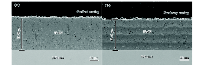
图2所示为梯度增加和循环增加N2流量时大厚度涂层的截面形貌。从图中可以看出, 大厚度涂层的截面比较平整光滑, 且基体与涂层在界面处结合良好, 厚度分别达到68.79 µm和64.48 µm。图2a的SEM结果表明, 梯度大厚度涂层中, 靠近膜基界面处存在较多大颗粒, 在N2流量较低的工艺下, 涂层致密性明显偏低, 我们认为大颗粒和部分空洞的存在有效地缓解了应力的累积, 熔滴尺寸大致在0.95 µm~10.33 µm范围内; 图2b中的SEM结果表明, 循环大厚度涂层展现出类似多层膜的结构, N2流量每个循环周期涂层的厚度大致相同, 沿涂层厚度方向大颗粒分布相对均匀。
图2 梯度增加(a)和循环增加(b) N2流量时大厚度涂层的截面形貌
Fig.2 SEM cross-section images of the coatings with large thickness deposited under gradient increasing (a) and circulatory increasing (b) the flow of N2
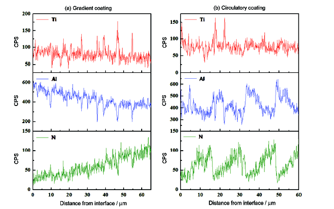
涂层成分沿厚度方向的分布如图3所示, Ti元素的含量沿涂层深度方向有微弱改变, 而Al元素和N元素的分布因工艺的调节发生了明显的变化。在梯度大厚度涂层中N元素的含量从膜基界面向表面逐渐增加, 相应的Al元素的含量逐渐减少, 这是由于界面处TiAl含量高, 随着N2流量增大, TiAlN越来越多, Al元素被N元素部分替代。在循环大厚度涂层中, 也呈现出同样的规律性。此外, 工作气氛总压的变化, 必然导致Ti、Al元素在到达涂层表面的过程中受到碰撞的变化, N2流量增加时, 总压升高, 涂层中金属元素的含量也随之下降。
图3 梯度增加(a)和循环增加(b) N2流量时大厚度涂层成分的沿层深分布
Fig.3 Composition distributions along the depth of the coatings with large thickness deposited under gradient increasing (a) and circulatory increasing (b) the flow of N2
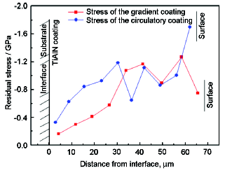
大厚度涂层残余应力沿层深分布趋势如图4所示。梯度增加和循环增加N2流量所制备的两种大厚度涂层, 在涂层生长过程中, 随着N元素含量的变化, 其残余应力沿层深方向逐渐累积而增大, 与前期研究中报道的硬质涂层应力沿层深分布趋势不相同[26], 由于涂层厚度较大, 以柱状晶为主要生长模式的涂层应力很难释放。随着膜层厚度的增加, 总体趋势展现出沿层深方向的应力逐渐增大, 梯度增加N含量和循环增加N含量, 虽然没有改变应力沿层深逐渐累积增大的趋势, 但是有效减缓了应力沿层深累积增大的速度。
图4 梯度增加和循环增加N2流量时大厚度涂层残余应力的沿层深分布
Fig.4 Residual stress distributions along the depth of the coatings with large thickness deposited under gradient increasing and circulatory increasing the flow of N2
在两种N2流量调节的工艺下, 两种涂层的残余应力始终处于较低水平, 其全膜厚平均应力分别为梯度大厚度-0.74 GPa, 循环大厚度-0.92 GPa, 折算为膜基界面剪切力[27], 梯度大厚度509 N, 循环大厚度593 N, 此水平与厚度为5 µm、残余应力-10 GPa的薄膜样品相当, 可见, 保持较低的残余应力是制备大厚度涂层的重要基础。
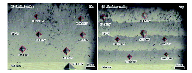
大厚度涂层的截面硬度如图5所示。由涂层/基体界面到涂层表面的方向, 图5a中涂层的截面硬度逐渐增大, 越靠近涂层表面, 其硬度值越大, 这与N元素含量增多, 氮化物增多趋势相一致。从图5b中可以明显看出明暗相间的多层结构, 硬度值的分布与N元素含量的循环相一致。测试两种大厚度涂层的表面硬度分别为 (1825.9±62) HV和 (1979.5±88) HV, 可以发现, 涂层表面硬度高于截面硬度, 这是因为涂层为柱状晶生长结构[26], 截面硬度测试从柱状晶的侧面压入, 而表面硬度测试从柱状晶的顶部压入。截面硬度可代表其硬度变化趋势, 表面硬度才是其真实硬度。
图5 梯度增加(a)和循环增加(b) N2流量时大厚度涂层截面硬度的沿层深分布
Fig.5 Cross-section microhardnessdistributions along the depthof the coatings with large thickness deposited under gradient increasing (a) and circulatory increasing (b) the flow of N2
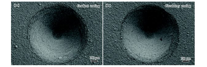
图6展示了大厚度涂层试样的洛氏压痕形貌。从图中可以看出, TiAlN大厚度涂层的压痕边缘出现了沿周向分布的环绕状裂纹, 环绕状裂纹的产生是由于涂层与基体弹塑性变形能力不同所致。已有研究指出[28, 29], 表面径向裂纹形成于加载半周期, 随着载荷加大而扩展, 而亚表面侧向裂纹起因于卸载过程中压痕塑性区与周围弹性区的弹性不匹配, 在残余应力作用下呈弧状向表面扩展, 形成周向环绕状裂纹。在图6中未见明显涂层脱落或径向裂纹, 说明大厚度涂层的断裂韧性比较好, 膜基结合力较好。
图6 梯度增加(a)和循环增加(b)N2流量时大厚度涂层的洛氏压痕形貌
Fig.6 Rockwell indentation morphology of the coatings with large thickness deposited under gradient increasing (a) and circulatory increasing (b) the flow of N2
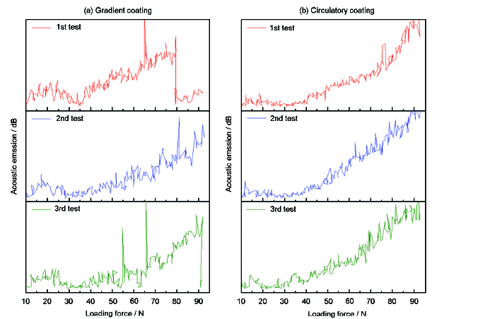
图7为大厚度涂层的膜基结合力划痕法测试结果。在梯度大厚度涂层测试中(见图7a), 当载荷达到55~65 N时, 声发射信号开始发生强烈的波动, 涂层发生破裂; 在循环大厚度涂层测试中(图7b), 随着载荷逐渐增加, 声发射信号逐渐增大, 未见强烈突变, 说明循环大厚度涂层具有更好的膜基结合力。测试结果表明, 本工作中两种工艺制备的TiAlN大厚度硬质涂层的膜基结合力良好。
图7 梯度增加(a)和循环增加(b) N2流量时大厚度涂层的划痕强度
Fig.7 Scratching test of the coatings with large thickness deposited under gradient increasing (a) and circulatory increasing (b) the flow of N2
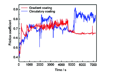
大厚度涂层的摩擦系数随时间的变化曲线如图8所示。从图中可以看到, 在最初的磨合阶段, 涂层的摩擦系数迅速增加, 主要是因为在初始的摩擦磨损过程中, 接触条件从两物体间磨料磨损逐渐转变为界面滑移[30]。经过1000 s的磨合期后, 梯度涂层逐渐达到平稳状态, 摩擦系数稳定在0.7~0.8之间, 而循环涂层的摩擦系数变化波动较大, 且表现出一定的周期性, 这是由于摩擦磨损过程中膜层被磨损, 与循环涂层成分的周期性分布有关。当摩擦磨损5000 s左右, 梯度大厚度涂层的摩擦系数降低至0.65左右, 这是由于随着磨损时间增加, 较硬的近表面层逐渐损耗, 同时伴有部分的氧化磨损, 导致摩擦副之间的界面变得平滑, 使摩擦系数得到降低。对比两种工艺涂层的摩擦系数曲线可以发现, 梯度大厚度涂层的摩擦系数低于循环大厚度涂层。
图8 梯度增加和循环增加N2流量时大厚度涂层的摩擦系数
Fig.8 Friction coefficientof the coatings with large thickness deposited under gradient increasing and circulatory increasing the flow of N2
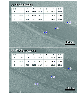
大厚度涂层经过120 min摩擦实验后的磨痕形貌及成分分析如图9所示。经SEM观察可以发现, 大厚度涂层的磨痕表面比较光滑平整, 且磨痕表面的粘附物和磨屑也较少, 说明TiAlN大厚度涂层具有良好的摩擦学性能, 且梯度增加N2流量时大厚度涂层具有更好的耐磨性。对大厚度涂层磨痕中的1、2、3点处分别进行EDX分析后发现, 在磨痕中心处的细小颗粒主要成分为TiAlN, 这些硬质颗粒导致了犁沟状磨痕的产生, 属于典型的磨粒磨损行为。而在磨痕边缘处出现了大量O元素和Si元素成分, 这是由于在摩擦磨损的过程中, 脱落的粘附物被挤压到磨痕边缘, 对磨副SiN磨球部分磨损残留了Si元素, 成分分析表明TiAlN大厚度涂层的磨损主要是磨粒磨损和氧化磨损共同作用。
图9 大厚度涂层经过120 min摩擦实验后的表面形貌及成分分析
Fig.9 Surface morphologies and components analysis of the coatings with large thickness after 120 min friction Test
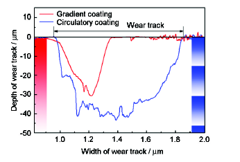
经摩擦磨损实验后, 大厚度涂层的磨痕轮廓比较清晰, 见图10。可以看出, 涂层的最大磨痕深度小于涂层的厚度, 说明经过120 min后摩擦磨损距离约为5426 m, 而大厚度涂层仍未磨穿, 展现出很好的耐磨性。循环大厚度涂层的磨痕截面面积明显大于梯度大厚度涂层, 这是由于循环大厚度涂层在厚度方向硬度循环变化导致的。经计算, 梯度大厚度涂层和循环大厚度涂层的磨损率分别为
图10 大厚度涂层经过120 min摩擦实验后的磨痕轮廓
Fig.10 Wear track profiles of the coatings with large thickness after 120 min friction test
1. N2流量对大厚度涂层成分的调节效果明显, Ti元素的含量沿层深分布变化不大, 而Al和N元素的含量随N2流量变化显著;
2. 大厚度涂层残余应力沿层深的分布, 总体趋势从膜基界面向表面逐渐增大, 梯度大厚度和循环大厚度涂层的全膜厚平均应力分别为-0.74 GPa和-0.92 GPa, 变化N2流量工艺有效降低了大厚度涂层的残余应力。
3. 大厚度涂层的截面硬度分布与N元素含量分布相一致, 梯度大厚度和循环大厚度涂层的表面硬度分别达到 (1825.9±62) HV和 (1979.5±88) HV; 结合力测试结果表明, 循环大厚度涂层具有更好的抗划痕能力和断裂韧性。
4. 大厚度涂层的磨痕表面比较光滑平整, 且磨痕表面的粘附物和磨屑也较少, 涂层具有良好的摩擦学性能, 且梯度涂层相比循环涂层具有更低的摩擦系数与磨损率, 表现出更好的耐磨性能。
The authors have declared that no competing interests exist.
| [1] |
Th. Schwarz, G. Kirchhoff, A. Mucha, A comparative study of the mechanical properties of TiN coatings using the non-destructive surface acoustic wave method, scratch test and four-point bending test,
Therefore TiN-coated steel (42CrMo4) samples with different states of adhesion were prepared. These samples were investigated by the SAW method, scratch test and four-point bending test. A significant correlation between the SAW results and the results of the destructive adhesion tests was found. The SAW method was shown to be complementary to the destructive adhesion tests. In addition, some results of the scratch test could only be explained by taking the SAW results into account.
|
| [2] |
Titanium aluminum nitride films: A new alternative to TiN coatings,
TiAl films have been produced in various compositions by using the sputter ion plating process. Filmssputtered reactively from a target with the composition of TiAl 50:50 at.65% have been deposited with a composition of 27.5 at.65% Ti, 28.9 at.65% Al, and 43.6 at.65% N. The crystal structure found was that of sodium chloride with a lattice parameter of 4.20 03; the microhardness such films was found to be HV 2100–2300. The incorporation of Al into the nitride films improves the oxidation resistance as well as the cutting performances of TiAlN coated drills. TiN films start to oxidize at a temperature level of 55065°C, whereas TiAl coatings react with hot air at a temperature of 80065°C severely. TiAlN coated drills have been tested with two different steels and performed better by a factor >2 compared with TiN coated drills.
|
| [3] |
Mechanical properties of ion-plated TiN films on AISI D2 steel,
TiN films were deposited on AISI D2 steel substrates without and with a titanium intermediate layer using a hollow cathode discharge (HCD) ion plating technique. The structure of the film was determined by X-ray diffraction (XRD) and the composition was measured by X-ray photoelectron spectroscopy (XPS). The microhardness and adhesive strength of the as-deposited coatings were measured as well. The results of X-ray diffraction and X-ray rocking curves showed that the TiN film exhibited a (111) preferred orientation. The hardness of coatings was found to be related to the N/Ti composition ratio and the porosity in the TiN films. The results of scratch test show that the high critical load is a measure of the adhesion of the TiN film, while the low critical load can be used as a qualitative measure of the toughness of the TiN film. The interfacial diffusion depth increased with the average substrate temperature during the ion plating process. From the results of scratch test and the depth profiles of secondary ion mass spectrometry (SIMS), the adhesive strength of the coating/substrate interface increased with increasing interdiffusion depth. Moreover, the results indicated that the Ti interlayer can enhance the adhesion strength of the coatings.
|
| [4] |
Application of Vickers indentation for assessment of PVD TiN coated new nonledeburitic high-speed steels,
The work is focused on the application of Vickers method for assessment of PVD coated high-speed steels. New grades of tailored carbide phase and commercial steels, both wrought and by powder metallurgy, were coated with titanium nitride. Indentations made at a wide range of loads were employed to obtain the coatings hardness using both theoretical models and an extrapolation method. On the basis of scanning electron microscope observations, fracture patterns were classified and quantitative criteria for their evaluation were suggested. The indentation measurements were used to assess the influence of the steel substrate material, coating thickness and presence of Ti underlayer on cohesion and adhesion of the coatings.
|
| [5] |
Phase formation and characterization of hard coatings in the TiAlN system prepared by the cathodic arc ion plating method,
Not Available
|
| [6] |
High-temperature oxidation of ion-plated TiN and TiAlN films,
|
| [7] |
High-temperature oxidation of Ti0.3Al0.2N0.5thin films deposited on a steel substrate by ion plating,
<a name="Abs1"></a>To improve the high-temperature oxidation resistance of STD61 steels used ashot dies or cutting tools, Ti<sub>0.3</sub>Al<sub>0.2</sub>N<sub>0.5</sub>films were deposited on STD61 steel substrates by arc-ion plating. Thedeposited film consisted of Ti<sub>3</sub>Al<sub>2</sub>N<sub>2</sub> andTi<sub>2</sub>N phases. The oxidation characteristics were studied attemperatures ranging from 700 to 900°C in air. The deposited STD61steels displayed excellent oxidation resistance up to 800°C, butexhibited large weight gains and breakaway oxidation at 900°C. Theoxidation products were primarily Fe<sub>2</sub>O<sub>3</sub>, TiO, TiO<sub>2</sub>,and <img src="/content/W1N5H2RR25051GQ7/xxlarge945.gif" alt="agr" align="BASELINE" border="0">-Al<sub>2</sub>O<sub>3</sub>, the relative amount of each oxidebeing dependent on the oxidation condition. Among various oxides, TiO<sub>2</sub>and <img src="/content/W1N5H2RR25051GQ7/xxlarge945.gif" alt="agr" align="BASELINE" border="0">-Al<sub>2</sub>O<sub>3</sub> were the major oxides at 800°Cfor at least up to 16 hr. However, at a higher temperature or a longeroxidation period, the significant outward diffusion of iron from thesubstrate resulted in the formation of iron oxides, together with otheroxides of Ti and Al.
|
| [8] |
Oxidation behavior of (Ti1-xAlx)N films perpared by r.f. reactive sputtering,
The as-deposited (Ti 1 61 x Al x )N films had the same crystal structure as TiN (NaCl type). Al atoms seemed to substitute for Ti in lattice sites. The preferential orientation of the films changed with the Al content of the film, x . Oxide layers of the films grew during annealing and became thicker as the annealing temperature increased. The thickness of the oxide layer grown on the film surface decreased with increasing Al content in the film. For high Al content films an Al-rich oxide layer was grown on the surface, which seemed to prevent further oxidation. All of the films, however, were oxidized by 900 °C annealing, even if the Al content was increased up to 0.55.
|
| [9] |
Advanced PVD-TiAlN coatings on carbide and cermet cutting tools,
Significant advances have been made in the process design and development of PVD-TiAlN coatings for carbide and cermet cutting tools. Higher plasma ionization in the TiAlN deposition process creates coatings with dense microstructure and excellent adhesion characteristics. The resulting new generation of PVD-TiAlN coatings provide increased productivity in a wide range of machining operations and work-piece materials. This paper discusses the characteristics of high-ionization TiAlN coatings and their performance in metal-cutting applications.
|
| [10] |
Tribological properties of (Ti, Al)N coatings deposited at different bias voltages using the cathodic arc technique,
A study was carried out to see the effect of substrate bias voltage on various tribological properties of (Ti,Al)N films deposited using the arc-PVD technique. Films were deposited at substrate biases of -30, -50, -100, -300 and -500 V. It has been found that the Al at.% decreases with an increase in bias voltage. The wear rate measured using a calo-wear test is at a minimum for the films deposited at -100 V bias voltage. Lattice strain and microhardness show a maxima at -100 V. It is observed that the number of macro particles on the surface increases with bias voltage for -30 and -50 V and decreases after -100 V. The Glancing-angle XRD shows the presence of the h-(Ti,Al)N phase at lower bias voltages. The color varies from bluish black (L=46.2, a*=-0.13, b*=-3.06) to brownish black (L=43.84, a*=2.39, b*=-1.53) as the bias voltage is increased. Oxidation and corrosion properties show marginal change with bias voltage.
|
| [11] |
Dry cutting performance of HSS twist drills coated with improved TiAlN,
PVD TiAlN coatings have been known for 10 years, particularly because of their high oxidation resistance. This specific property favours them in dry cutting operations. TiAlN coatings grown by combined steered arc/unbalanced magnetron (UBM) deposition show a considerable concentration of growth defects stemming from the adhesion enhancing cathodic are TiAl metal ion-substrate etching prior to the UBM magnetron coating step. Thus the roughness of 3 m thick purely UBM deposited TiAlN coatings is enhanced from R= 0.04 m to R= 0.18 m. The roughness of these coatings may be reduced to R= 0.05 m, if Cr is used as metal ion etching vapour instead of TiAl. The hardness of TiAlN coatings can be increased from typically HK3000 to approx. HK3300 by adding C (reactively) into the near surface region of the film.Laboratory and industrially scaled dry drilling tests have been carried out in cast iron GG25. Reducing the surface roughness of the coatings doubles the lifetime of ADX drills when operated at 60 m mincutting speed. The lifetime is further doubled by the addition of C. In professional and industrial drill tests the new ''smooth'' TiAlN coated drills clearly outperform most of the purely arc coated tools.
|
| [12] |
Ti, Cr)N and Ti/TiN PVD coatings on 304 stainless steel substrates: Texture and residual stress,
Growth texture and residual stress were determined by X-ray Diffraction (XRD) methods in three different nitride coating systems (TiN or (Ti,Cr)N single-layers and TiN/Ti two-layers) deposited by reactive sputtering on AISI 304 stainless steel. All samples exhibited the fibre texture typical of many PVD layers grown under non-epitaxial conditions, and the nitride layer had the well-known fcc structure of δ -TiN. The main growth direction in TiN coatings (independently of the presence of the Ti buffer) was [111], even if a secondary [211] grain fraction was produced by a twin growth mechanism that partially relaxed the intense compressive stress (≈ 61 8 GPa). The Ti buffer layer, also in a compressive state, contributed to a further reduction of the in-plane compression in the TiN top coat. The residual stress in the (Ti,Cr)N coatings was very high (≈ 61 17 GPa), probably due to the different growth texture (nearly [h00]) and the absence of suitable stress relaxation mechanisms.
|
| [13] |
Effects of nitrogen pressure and pulse bias voltage on the properties of Cr-N coatings deposited by arc ion plating,
Cr–N coatings were deposited on 1Cr18Ni9Ti stainless steel in the pure N 2 atmosphere by arc ion plating (AIP). The relationships between deposition parameters and coating properties were investigated. X-ray diffraction showed a phase transformation from CrN+Cr 2 N+Cr→CrN+Cr→CrN and the CrN preferred orientation changed from (200) to (220) as N 2 pressure increased. Increasing bias voltage led to CrN preferred orientation changed from (200) to (220) and the formation of Cr 2 N. XPS results indicated that chemical composition of the coatings changed as N 2 pressure increased but it changed little with bias voltage. The lower melting point of chromium nitride formed on target surface induced the increase of macroparticles and deposition rate with increasing N 2 pressure; and bias voltage had an obvious effect on reducing macroparticles of the Cr–N coatings. Residual stresses were measured by substrate curvature technique, and the changing tendency coincided with the microhardness of the coatings.
|
| [14] |
Influence of substrate bias voltage on the microstructure and residual stress of CrNfilms deposited by medium frequency magnetron sputtering,
In this study, the influence of cobalt (Co) on the microstructure and adhesion between enamel and steel substrate has been investigated. The result of press test indicated that the adhesion strength was greatly improved by Co inclusion. Scanning electronic microscope (SEM)revealed that the amount of dendrite increases in the interface while its average size decreases. The wavelength dispersive X-ray analysis (WDS) identified the existence of Co in the dendrite, which confirms that the Co was closely related to the change of interface morphology and the improvement of adhesion strength. Finally, the reasons for adhesion improvement were discussed.
|
| [15] |
Multilayer TiAlN coatings with composition gradient,
ABSTRACT The fuzzy-logic process control system has been adapted to the unbalanced magnetron reactive sputter deposition of Ti161xAlxN coatings. This made possible the dynamic control of the deposition rate, chemical composition and structure of the coatings and provided stable working conditions inside the hysteresis loop of the reactive sputtering also. By applying this control system, multilayers of micro- and nanocrystalline composite structures were prepared with compositions of Ti39Al61N and Ti56Al44N of TiN–AlN cubic solid solution phases.
|
| [16] |
Influence of Ti/TiAlN-multilayer designs on their residual stresses and mechanical properties,
In this research work, Ti/TiAlN multilayers of various designs were deposited onto substrates pretreated by different etching procedures. The influence of multilayer design and substrate pretreatment on multilayers adhesion, hardness, wear and friction coefficients was systematically analyzed and correlated with residual stresses of these multilayers as well as with residual stresses on the coating-near substrate region, which were analyzed by synchrotron X-ray diffraction at HZB-BESSYII. These investigations show that the adhesion can be improved by a specific etching procedure, which cause increased compressive stress in the coating-near the substrate region. Additionally, it was found, that the multilayer with the thickest ceramic layers has the highest hardness and the lowest wear coefficients as well as the lowest compressive residual stress within studied multilayers. (C) 2011 Elsevier B.V. All rights reserved.
|
| [17] |
Modification of stress distribution along the thickness of (Ti, Al)N coatings and Preparation of the coatings with large thickness, Ti, Al)N涂层应力沿层深分布的调整及大厚度涂层的制备,
利用电弧离子镀技术在不锈钢基体上制备了(Ti, Al)N涂层, 研究了N<sub>2</sub>分压改变对涂层残余应力沿层深分布及相关</br>力学性能的影响. 结果表明, 低N<sub>2</sub>分压下, (Ti, Al)N涂层残余应力沿层深分布较均匀, 随N<sub>2</sub>分压的增加, 涂层应力沿层深呈</br>“钟罩型”分布, 且全膜厚的应力值也明显增大; 通过对涂层生长结构及微观成分分析, 初步探讨了应力分布机理. 随N<sub>2</sub>分压的增</br>加, 涂层硬度会显著增加, 而膜/基结合力则大幅下降; 采用改变N<sub>2</sub>分压工艺制备(Ti, Al)N涂层, 可有效调整涂层残余应力沿</br>层深分布趋势, 改善其力学性能, 并可成功制备厚度在130 <em>μ</em>m以上的硬质涂层.
|
| [18] |
Preparation of wear-resistant graded metal-ceramic coating by laser-alloying,
激光合金化熔覆制备耐磨陶瓷梯度涂层,
利用预涂敷与激光重熔方法制备陶瓷梯度涂层,并对涂层的冶金结构,组成,硬度,以及耐磨性进行分析,结果表明,该涂层内陶瓷硬质相体积百分比沿基体到表面方向呈梯度变化,过渡层为具体良好韧性的固溶体,涂层结构均匀,和基体结合良好,无气孔和裂纹,厚度为0.4-0.8mm,表层硬度达HV0.21100与普通与激光涂层比较,涂层内部的硬度随着成分组成的变化而平缓变化,既提高了涂层与基体的结合强度又提高了表面的耐磨
|
| [19] |
Properties of single layer and gradient (Ti, Al)N coatings,
This paper discusses the deposition parameters and the properties of cathodic arc deposited single layer and gradient (Ti,Al)N coatings using TiAl cathodes. We noted that the bias voltage had a significant influence on the formation of macro droplets and the number of macro droplets decreased with increasing bias voltage. The hardness decreased with increase of bias voltage from 6175 to 61300 V and a maximum hardness of 2783±25 HV was achieved at 6175 V and at a N 2 pressure of 0.66 Pa. The adhesion strengths of (Ti,Al)N coatings deposited on M2 steels were in the range of 44–92 N (Lc 1 ). A high adhesion strength of 92 N (Lc 1 ) was observed for a coating deposited at 6175 V and at 1.33 Pa of N 2 . Gradient coatings deposited by continuously varying the bias voltage during the deposition of coatings exhibited higher values of critical loads of adhesion (Lc 1 in the range of 87–97 N and Lc 2 >120 N) for both positive and negative gradient coatings. The higher critical loads of adhesion observed for gradient (Ti,Al)N coatings suggest that there is an excellent potential to further enhance the wear properties of (Ti,Al)N coatings.
|
| [20] |
Effect of Ti interlayer on the residual stress and texture development of TiN thin films deposited by unbalanced magnetron sputtering,
ABSTRACT The purpose of this study was to investigate the effects of Ti interlayer on the texture and residual stress of overlaying titanium nitride (TiN) thin films. Films were deposited by ion-beam assisted deposition (IBAD) on substrates with or without a Ti interlayer. Residual stresses and pole figures of the grown films were measured by X-ray diffraction (XRD) techniques. Thin films with either in-plane or fiber textures were produced. Results showed that the Ti-interlayer had the effect of changing the in-plane texture. The in-plane texture was switched from the Type 3 texture, where the was along the 45掳 incident ion beam and the (111) planes were 45掳 to the film surface, to the Type 1 texture, where the grain orientation rotates 45掳 along the axis with respect to the Type 3 texture. For a strongly (0002) textured Ti-interlayer, alignment of the (111) plane in TiN was found. For films with fiber texture, the use of a Ti interlayer changed the texture of the TiN film; and a strongly (0002) textured Ti interlayer was necessary to align the texture of the TiN film with the underlayer. The effect of Ti interlayer on the change of TiN texture is most evident for films with loose packing or low residual stress.
|
| [21] |
The performance and degradation behaviours of the TiAln/interlayer coatings on drills,
TiAlN/interlayer coatings on drills were investigated for the coating characteristics and drilling performance. The interlayers investigated include TiN, TiAl, and electroless Ni-P. The coating characteristics and wear behaviour of the coatings during a drilling test were studied with XRD, XPS, and SEM. It was found through XPS that a greater binding energy of the coating elements leads to a longer tool life for the drill. The factors which affect the drill performance also include the bonding behaviour between coating and interlayer.
|
| [22] |
Improvement of the interfacial integrity of (Ti, Al)N hard coatings deposited on high speed steel cutting tools,
Deposition of both interlayer and (Ti,Al)N films was conducted sequentially in a single batch process, while cathodic arc evaporation was selected as the deposition method for its superior plasma intensity and the flexibility of multiple target arrangement. Microstructure and tribological properties were analyzed by scanning electron microscopy/electron diffraction spectroscopy, particle analyzer, microhardness and wear testers. Results indicated that a combination of TiN and TiAlN interlayers provided an adhesion strength of 50聽N between (Ti,Al)N and M2 substrates. The tribological performance of (Ti,Al)N thin films on high-speed steel cutting tools was significantly improved.
|
| [23] |
Hardness and residual stress in nanocrystallineZrN films: Effect of bias voltage and heat treatment,
The purpose of this study was to investigate the effects of both bias voltage and heat treatment on the composition, microstructure, and associated mechanical properties of the zirconium nitride (ZrN) thin films deposited on AISI 304 stainless steel substrates by a filtered cathodic arc ion-plating (FCA-IP) system. The depositions were carried out by varying negative substrate bias voltage, from 614002V b to 618002V b . The deposited film specimens were heat-treated at 80002°C for 102h. X-ray diffraction (XRD) revealed that (a) texture coefficients of (1021021) plane increased with negative bias, and (b) the grain size was approximately less than 1502nm, i.e. nano-scale grain size. The hardness of the deposited ZrN films was correlated with point defects, (1021021) texture coefficient, and crystallinity characterized for the films. For the as-deposited films, it was found that the hardness increased with decreasing (1021021) full width of the peak at half maximum (FWHM) and increasing (1021021) texture coefficient, suggesting a better crystallinity and lower grain boundary mobility in the highly textured films. The decrease in film hardness after heat treatment may be attributed mainly to the reduction of point defects present in the films. Measurements performed for the intrinsic residual stress reported a significant 5.502GPa release in the heat-treated films, due to recovery of point defects by heat treatment.
|
| [24] |
The depth distribution of residual stresses in (Ti, Al)N films: Measurement and analysis,
A method is introduced to determine the depth distribution of the residual stresses in (Ti,Al)N films. The films were gradually stripped by chemical corrosion, an optical system was designed to test the curvature change of the specimens, and the depth distribution of the residual stresses was calculated. The results show that the residual stresses increase gradually from the interface of film/substrate and reach a maximum value at the middle region, then decrease until the surface.
|
| [25] |
Evaluation of PVD nitride coatings, using impact, scratch and Rockwell-c adhesion test,
The studies demonstrate the usefulness of using these test methods for differentiating between the behaviour of different coatings under various contact conditions.
|
| [26] |
Effect of deposition processes on residual stress profiles along the thickness in (Ti, Al)N films,
The effect of deposition processes on the distribution of residual stresses in the thickness of the (Ti,Al)N films prepared by arc ion plating (AlP) was investigated in the present work, which indicates that the stress distribution exhibits a "bell" shape and the maximum compressive stress appears in the layer near the surface. The residual stress increases with the thickness of a film and the substrate bias voltage, respectively. The stress distribution can be altered, and the adhesion of the film/substrate can be improved by optimizing the deposition parameters. Finally, a film with a thickness of 7.57 mu m was successfully directly deposited on the substrate through optimizing the bias voltage. (C) 2008 Elsevier B.V. All rights reserved.
|
| [27] |
Effects of TiN Films Thickness on Mechanical Properties of Stainless Steel, 厚度对TiN薄膜力学性能的影响,
采用电弧离子镀方法制备了不同厚度TiN薄膜,并对其硬度、结合力、残余应力、摩擦磨损特性等力学性能进行了系统性研究,以揭示硬质薄膜厚度对其力学性能的影响规律。结果表明,随着厚度增加,薄膜表面大颗粒增加,膜基界面剪切力增大,薄膜硬度逐渐增加,结合力逐渐下降,摩擦系数略有下降;而薄膜应力沿层深分布趋势基本一致,都呈钟罩形分布;磨损率随薄膜厚度变化不大,即薄膜越厚越耐磨。
|
| [28] |
Microfracture beneath point indentations in brittle solids,
The microfracture patterns observed around point indentations in brittle solids are investigated. A description is first given of the stress field in an elastic half-space loaded normally at a point in its surface. This field is then used as a basis for analysing the crack geometry. A localized zone of irreversible deformation forms about the contact point, thereby removing a singularity in the elasticity solutions and providing nucleation centres for the ensuing microcracks. Generally, two main types of ‘vent’ cracks are observed to propagate from the deformation zone: median vents, formed during indenter loading, spread downward below the point of contact on planes of symmetry, and lateral vents, formed during unloading, spread sideways toward the specimen surface. Of these, the median vent is relatively well-behaved, and is amenable to standard fracture-mechanics analysis. From such an analysis we derive the means for predetermining, in principle, the depth of fracture damage under given point loading conditions. The significance of the results in relation to important practical applications, such as glass cutting and surface fragmentation processes, is discussed.
|
| [29] |
Vickers indentation fracture toughness test Part 2 Application and critical evaluation of standardised indentation toughness equations, |
| [30] |
Effects of Cr interlayer on mechanical and tribological properties of Cr-Al-Si-N nanocomposite coating,
Cr-Al-Si-N coatings were deposited on SUS 304 substrate by a hybrid coating system. A Cr interlayer was introduced between Cr-Al-Si-N coating and SUS 304 substrate to improve the coating adherence. The effects of Cr interlayer on the microhardness, adhesion, and tribological behavior of Cr-Al-Si-N coatings were systematically investigated. The results indicate that the microhardness of the Cr-Al-Si-N coatings gradually deceases with increasing thickness of Cr interlayers. The adhesion between Cr-Al-Si-N and SUS 304 substrate is improved by addition of the Cr interlayers. A peak critical load of 6550 N is observed for the coating containing Cr interlayer of 60 nm as compared 65 20 N for the coating without Cr interlayer. The thicker Cr interlayers result in reduced critical load values. Moreover, the wear resistance of the Cr-Al-Si-N coatings is greatly enhanced by introducing the Cr interlayer with thickness of 60 nm in spite of the decreased microhardness. The friction coefficient of the coating system is also moderately reduced.
|
| [31] |
On tribologicalproperties of PVD thick CrNcoating in seawater environment, PVD大厚度CrN涂层海水环境摩擦学性能研究,
试验采用一种大厚度CrN涂层对海洋设备关键摩擦副零部件进行表面防护。对该涂层进行系统的表征,并用UMT-3往复式摩擦磨损试验机进行海水环境中摩擦磨损性能测试。结果表明,该涂层厚度约为7 m,其大气环境中的摩擦系数大于在海水和纯水中的摩擦系数,这是由于溶液中的水分子在一定程度上起到了边界润滑的作用。在海水环境中CrN涂层的磨损率低于大气和纯水中,这归因于海水中的低摩擦系数以及CrN涂层良好的耐蚀性。涂层海水中的磨损率约为同条件下316L不锈钢的20%,具有明显的减摩耐磨效果。
|

/
| 〈 |
|
〉 |