



航空发动机,被誉为飞机“皇冠上的明珠”[1]。镍基高温合金可用于制造飞机的发动机[2]、燃烧室罐、机舱加热器、尾管、过渡导管、喷嘴以及火焰架[3~5],可用电阻点焊连接这些部件。电阻点焊是一种热输入集中的高速焊接工艺,能高效率连接飞机的部件[6]。为了得到良好的镍基高温合金电阻点焊工艺参数,袁荣等[7]建立多焊点焊接模型,研究了焊接参数对熔核尺寸的影响,以及焊点数量和焊点间隙对构件形变的影响。Martín等[8]研究了电阻点焊和沉淀硬化对A286高温合金构件拉剪承载能力的综合影响。Bemani和Pouranvari[9]研究了Nimonic 263与GH3536镍基高温合金的异材电阻点焊接头,发现超高速冷却在枝晶间区域生成富钼碳化物而形成超细枝晶结构,使焊点接头的力学性能显著提高。在航空制造领域,作为电阻点焊关键耗材的电极,其频繁维修影响生产效率,因此须深入研究电极材料[10~12]和电极寿命[13]。罗平等[14]研究了CrZrCu电极失效的原因。张勇等[15]研究了CrZrCu电极、BeCoCu电极的形貌和熔核直径。韩强等[16]对Al2O3弥散强化铜电极进行了失效分析。王孟君等[17]概述了弥散强化铜电极的制备。
1 实验方法
实验中用电阻点焊连接GH3536镍基高温合金构件。电阻点焊机由电极、加压机构、焊接电源和控制系统等组成。实验用GH3536镍基高温合金构件的化学成分列于表1,构件试样的屈服强度为430 MPa,抗拉强度为840 MPa,延伸率为48%,硬度为260HV。构件试样的尺寸为125 mm × 25 mm × 1.3 mm。
表1 GH3536合金的化学成分
Table 1
| Material | Cr | Fe | Mo | W | Co | P | Al | Ni | Mn | Si | C |
|---|---|---|---|---|---|---|---|---|---|---|---|
| GH3536 | 21.77 | 18.86 | 8.42 | 0.908 | 0.980 | 0.011 | 0.164 | Bal. | 0.696 | 0.262 | 0.071 |
用三相次级整流电阻点焊机点焊GH3536镍基高温合金构件。电阻点焊机的型号为DZ-3×100,气动、活塞式加压模式,功率为300 kVA,最大电极压力为30 kN。实验用BeCoCu铜棒电极的直径为15 mm,端部结构为球形,球面半径为SR150 mm (图1),BeCoCu电极的化学成分中Be的质量分数为0.35%,Co的质量分数为1.5%,余量为Cu。
图1

电阻点焊1.3 mm厚GH3536合金构件试样的工艺参数为:预压时间t0为400 ms,焊接压力F为10 kN,焊接电流I1为8.5 kA,焊接时间t1为400 ms,锻压Ff为14 kN,缓冷电流I2为6 kA,缓冷时间t2为200 ms,维持时间t3为400 ms,休止时间t4为1800 ms。
使用线切割将第N (N = i × 20,i = 1, 2, 3,……,20)个焊点沿熔核中心切开,用砂纸将其研磨后抛光,用王水(3 mL HCl + 1 mL HNO3)将其腐蚀后测量熔核直径并观察内部缺陷;使用WDW-100型电子万能实验机对第N-1和第N+1个焊点进行拉伸实验,拉伸速度为2 mm/min。取多次实验所得数据的平均值。
用金相显微镜(OM,MR5000)、扫描电子显微镜(SEM, Phenom XL G2)、X射线衍射仪(XRD, D8ADVANCE)、能谱仪(EDS, Axis Ultra DLD)、和电子背散射衍射(EBSD, Velocity Plus)等手段表征失效电极,以揭示其失效机制。表征的评判标准是GJB 724B-2019《钢及高温合金电阻焊工艺及质量检验》[21]。为了保证焊点的质量,熔核尺寸的最小值为4.7 mm,抗拉强度为840 MPa时单点焊最小拉剪力为7 kN。
2 结果和讨论
2.1 电极的寿命
图2
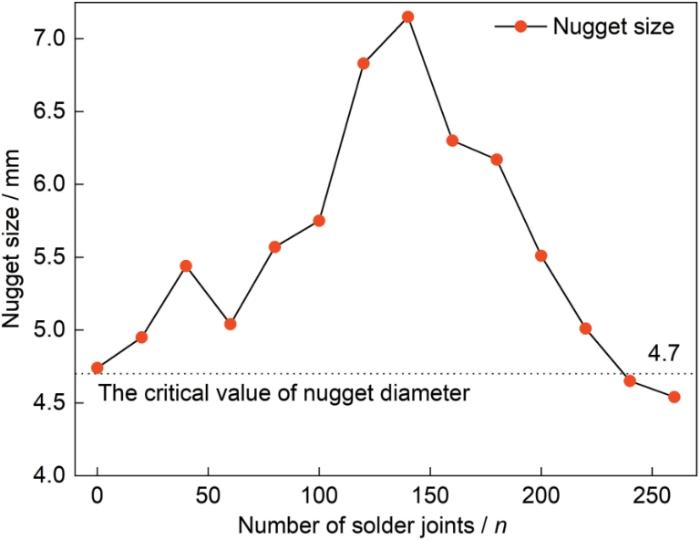
图2
熔核直径与焊点个数的关系
Fig.2
Relationship between the nugget diameter and the number of solder joints
图3

图3
拉剪力与焊点个数的关系
Fig.3
Relationship between the tensile shear force and the number of solder joints
用BeCoCu电极点焊GH3536合金时,其熔核直径随着焊点个数的增加呈现先增加后减少的趋势,其原因是电极端面的形态和状态的变化使产热与散热的动态平衡发生了变化。在第140个焊点之前,电极球面焊接后形成稳定的小平面,电极与试样接触面积的增大使电流分布更均匀、热输入更有效,从而使熔核直径增大和焊点个数达到(最大值) 140点;焊点个数的持续增加使电极的接触面积过大和电流密度显著降低且散热加快。同时,电极的合金化使其性能降低。这些因素导致产热不足,从而使熔核直径减小,拉剪力也随着焊点个数的增加呈先增加后减少的趋势。在第80个焊点前,熔核尺寸是影响拉剪力的主要因素,拉剪力随着熔核尺寸的增加而增大;在第80个焊点后,可能是电极表面合金化和晶粒的增大恶化了电极的工作状态,导致试样的拉剪力降低。在第240个焊点拉剪力仍然合格,所以根据熔核直径的评判标准,其对应的焊点数量作为该电极的最终服役寿命,即电极的寿命点数为220点。
2.2 电极的微观组织
图4
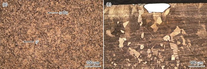
图4
失效前后电极端面的微观形貌
Fig.4
Microstructure of electrode end face before (a) and after (b) failure
2.3 电极失效后端面的形貌
图5
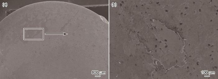
图5
电极端面的SEM形貌
Fig.5
SEM morphology of electrode end face (a) overall diagram, (b) partial enlarged view
2.4 电极端面的元素
图6
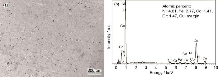
图6
电极端面的EDS分析
Fig.6
EDS analysis of electrode end face (a) electrode end face, (b) energy spectrum
在焊接过程中,Fe、Ni、Cr等元素向电极扩散与Cu结合生成IMCs,因与Cu基体的结合力较小,在焊接热应力和电极压力的作用下易产生微裂纹并脱落,暴露出的Cu基体与Fe等元素接触重复“扩散-合金化-脱落”过程,对电极的持续消耗形成宏观磨损。此前观察到的电极端面“金属粘连”,是Cu与(Ni, Fe, Cr)形成未完全脱落的脆性合金层。这种脆性合金层既破坏了电极的导电均匀性增大了接触电阻,又改变电极形貌而加速了磨损。
2.5 电极端面的物相组成
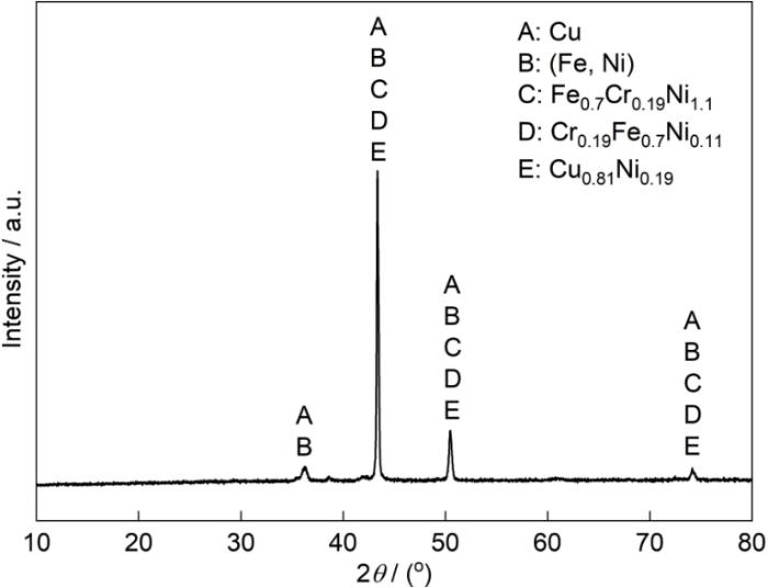
图7给出了失效电极的XRD谱,可见失效电极的主要物相有Cu单质、(Fe, Ni)置换固溶体、Fe0.7Cr0.19Ni1.1、Cr0.19Fe0.7Ni0.11以及Cu0.81Ni0.19等IMCs。在焊接过程中,Ni、Fe、Cr与Cu合金化生成脆性IMCs导致电极强度降低和脆性提高,导电率远低于纯Cu的合金化产物使电极与试片接触电阻增大。根据Joule定律,产热的进一步增加促进了界面元素扩散,提高了界面化合物的生成率而加速了电极的失效。
图7
2.6 BeCoCu电极的电子背散射衍射分析
图8给出了失效前后BeCoCu电极的反极图(Inverse pole figure, IPF)。如图8a所示,原始电极的微观结构由均匀细小的晶粒组成,其平均尺寸为4.06 µm,没有明显的颜色占比突出和择优取向,表明其各向同性良好和性能稳定。如图8b所示,在焊接热-力-电耦合作用下失效后的电极中的晶粒异常长大,平均晶粒尺寸增至11.48 µm,使微观结构出现不均匀性而形成以(111)为主的晶粒取向,在一定程度上优化了局部性能[23]。面心立方(fcc)结构的电极中(111)取向的原子排列最紧密难以滑移,增强了其表面抗变形能力以减缓端面直径的增大,从而维持了焊接过程中的结构稳定性、散热效率与电流密度。但是,晶粒的剧烈粗化使电极的宏观性能退化,导致其强度、硬度及塑性比原始状态显著降低,最终加速了电极在循环服役中的失效。
图8
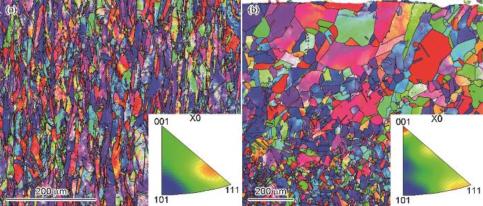
图8
电极的反极图
Fig.8
Inverse pole figure of the electrode before (a) and after (b) failure
图9

图9
失效前后电极端面的PF和ODF
Fig.9
PF (a, c) and ODF (b, d) of electrode end face before (a, b) and after (c, d) failure
焊接过程中的高速冷热循环使电极内的储存能反复积累和释放,使晶粒的长大破坏了原始的纤维状织构,从而使整体织构强度大幅度降低。焊接压力使端面发生塑性变形,晶粒转向更稳定的滑移方向而形成了以Cubic<111>||ND为主的织构混合体,使强度降低。在fcc结构的BeCoCu电极中,原始的Cubic{100}<001>和{110}<100>织构其主导取向<001>是“软取向”。这种“软取向”有利于晶格滑移,使电极具有良好的塑性变形性能;而失效后形成的Cubic<111>||ND织构取向<111>是密排方向,沿此方向启动滑移所需的临界分切应力较高,是典型的“硬取向”。这种“硬取向”严重阻碍滑移系移动,使电极在循环焊接压力下不能发生塑性变形协调应力,从而使微裂纹萌生的倾向提高而加速了电极失效。电极端面粗大的晶粒和低强度、不利的织构加速了电极的软化、磨损和变形,最终使电极失效。
图10中对比了BeCoCu电极失效前后晶界(Grain boundary, GB)的分布和取向差概率分布。可以看出,电极失效前后取向差为2°~15°的小角度晶界(Low-angle boundaries, LABs)其占比分别为47%和24%,大于15°的大角度晶界(High-angle boundaries, HABs)占比分别为53%和76%。原始BeCoCu电极内的高密度位错重组,形成了高密度的LABs。这种高位错密度和亚晶结构是材料发生塑性变形后的典型特征。焊接热循环和压力的共同作用,使这些LABs吸收和重组位错且其取向差逐渐增大,最终转变为HABs。
图10

图10
电极失效前后的晶界图和取向差概率分布
Fig.10
Grain boundary diagrams (a1, b1) and probability distribution diagrams (a2, b2) of orientation difference before (a1, a2) and after (b1, b2) electrode failure
HABs疏松的结构和高密度缺陷,使元素扩散所需的激活能比LABs的低,为GH3536合金中的Ni、Fe、Cr等元素向Cu电极内扩散提供了高速迁移通道。这些偏聚在晶界处的元素与Cu基体发生合金化生成了硬而脆的IMCs,使电极在应力作用下更易沿晶界萌生裂纹。同时,IMCs使电阻增大,导致焦耳热增加而使电极端面的晶粒增大和表面合金化速度提高,加速了电极的失效。
在电阻点焊过程中GH3536高温合金中的Fe、Ni、Cr等元素向电极内扩散,Fe元素因其原子半径与Cu相近而扩散最快;这些元素与Cu基体反应形成(Fe, Ni)固溶体和脆性IMCs,使电极表面的合金层粘连、萌生微裂纹和剥落。同时,焊接热‑力‑电循环使电极端面的晶粒显著粗化(平均尺寸由4.06 μm增至11.48 μm)、小角度晶界向大角度晶界转变和织构由强度高的Cubic{100}<001>和{110}<100>织构向强度低的Cubic<111>||ND织构转变,织构强度从4.12和5.62降低到3.05。这些微观结构的劣化和界面合金化,使电极的导电性、强度和塑性降低,最终第240焊点因熔核尺寸过小而失效。
3 结论
(1) BeCoCu电极点焊GH3536合金板的服役寿命为220点,熔核直径和抗剪切力都随着焊点个数的增加先增大后减小。失效后电极端面晶粒粗化,在其表面出现金属粘连。BeCoCu电极点焊GH3536合金板易发生合金化,使电极的磨损加速。
(2) BeCoCu合金电极失效后由强度较高的Cubic{100}<001>和{110}<100>织构转变为强度较低的Cubic<111>||ND织构,HABs含量的提高使电极合金化,从而加速电极的失效。
参考文献
Research progress of thermal barrier coatings for aeroengine turbine blades
[J].
航空发动机涡轮叶片热障涂层研究进展
[J].
High temperature oxidation of a HIPed nickel-based superalloy
[J].
A Ni-based alloy Ni-(12~18) Cr, (10~14) Co, (2~6) W, (2~6) Mo, (2~6) Ti, (2~6) Al was prepared via hot isostatic pressing by 150 MPa at 1150 oC with its argon gas atomization powders as raw material. Then its oxidation behavior in air at 950 oC was studied by intermittent weighing method in terms of the oxidation kinetics, phase composition, microstructure and elemental distribution of oxide scale and characteristics of oxygen-affected zone etc. The results show that the oxidation resistance of the as-HIPed superalloy at 950 oC has reached the full oxidation resistance grade in accord with the national standards. Both the oxidation kinetics curve and the depth variation curve of oxygen-affected zone follow a parabolic law. In the early stage of oxidation, Ti and Al atoms in the matrix diffuse rapidly along the prior particle boundaries (PPB) towards the alloy surface and form a continuous mixed oxide layer of Cr2O3, TiO2 and Al2O3. However, oxygen atoms diffuse inward along the PPB and undergoes in-situ oxidation reaction with secondary phases to form granular internal oxide Al2O3. After 24 hours oxidation, the surface oxide scale consists of the outmost layer of mixed oxides TiO2 and Al2O3, and the inner layer of Cr2O3 oxide. The continuous internal oxides TiO2 and Al2O3 appear in Cr-depleted zone. In the later stage of oxidation (> 100 h), the outmost TiO2 oxide layer peels off from the alloy surface, and the internal oxides TiO2 and Al2O3 distributed in Cr-depleted zone in a continuous root-like manner. Finally, the high temperature oxidation mechanism and formation process of internal oxides in as-HIPed nickel-based superalloy was also discussed.
热等静压态镍基高温合金的高温氧化
[J].研究了热等静压态镍基高温合金的高温氧化动力学、氧影响区的特征、相组成、微观形貌和元素分布,总结了高温氧化特征和内氧化物的生成过程。结果表明,这种热等静压态高温合金在950 ℃的氧化属于完全抗氧化级别,其氧化动力学曲线和氧影响区深度的变化曲线都符合抛物线变化规律。在氧化初期,合金基体中的Ti、Al离子沿原始颗粒边界(PPB)向表面快速扩散并生成连续的Cr2O3、TiO2和Al2O3混合氧化层,而氧原子沿PPB向内扩散与第二相发生原位氧化反应生成颗粒状内氧化物Al2O3。氧化24h后合金表面的氧化层由最外部的TiO2、Al2O3混合氧化层和底部的Cr2O3氧化层组成,在贫铬区出现连续的内氧化物TiO2和Al2O3。在氧化后期(氧化时间超过100 h)合金表面氧化层中最外部的TiO2氧化层脱落,贫铬区中的内氧化物TiO2和Al2O3呈连续树根状分布。
Investigation of the occurrence of hot cracking in pulsed Nd-YAG laser welding of Hastelloy-X by numerical and microstructure studies
[J].The hot cracking characteristic of the welded Hastelloy X is studied through the metallographic investigation of the weld zone and the thermo-mechanical modeling of the pulsed Nd-YAG laser process in SYSWELD (TM). The location of liquation cracking is determined by the incorporation of precipitation and the microstructure evolution of Hastelloy X and the temperature and stress profiles of the weld regions. The results reveal that increasing the speed of welding, with the maintenance of the penetration depth of the weld, leads to a decrease in liquation cracking in the heat affected zone. Microstructural evaluation indicates that solidification cracks are initiated from liquation cracks in the base metal and are propagated intergranular along the grain boundaries of the weld metal. It is also shown that the healing of liquated grain boundaries through backfilling can have a significant role in the resistance to liquation cracking in the heat affected zone and that, in turn, can affect tendency for solidification cracking in the weld metal. The analysis of the simulation identifies for d epsilon/dT higher than 0.007 (10(-3)/degrees K), the hot cracking is initiated in the middle zone of weld pool vicinity, where the strain rate was maximum.
Mechanical property study on rapid additive layer manufacture Hastelloy® X alloy by selective laser melting technology
[J].
First-principles-aided design of a new Ni-base superalloy: influence of transition metal alloying elements on grain boundary and bulk cohesion
[J].
Microstructure and mechanical properties of resistance spot welding joints for SUS301L stainless steel
[J].The microstructure, micro zone properties, fracture morphology, and mechanical properties of different areas for the resistance spot welding joint of SUS301L stainless steel are systematically characterized via microhardness tester, electronic tensile shear testing machine, SEM, and IBIS. The results indicate that the morphology of the fusion zone in the joint is elliptical and which can be differentiated into the base metal zone, heat affected zone, and nugget zone. The microstructure distribution from the edge of the fusion core to the core center is columnar structure and equiaxed structure in sequence. The main defects of the joint include sputters on the edge of the fusion core, shrinkage porosity in the fusion core, and micro cracks, and the sputtering phenomenon is closely related to the occurrence of shrinkage porosity. The size of the nugget diameter is a key indicator that affects the mechanical properties, and there is a positive correlation between the two. As the thickness of the double-layer plate increases, the maximum tensile and shear force increment caused by the increment of the unit nugget diameter also significantly increases. The hardness and strength of the heat affected zone are lower than those of the base metal zone and the fusion zone, which leads to the formation of a softening zone at the corona bond. Due to the lower strength of this zone, the tensile shear force it can bear is relatively small, making it the starting area for tensile shear cracking. The forms of tensile shear fracture may be differentiated into passing through-core fracture and along-core fracture, the nugget diameter will affect the fracture mode of the joint.
SUS301L不锈钢电阻点焊接头的微观组织和力学性能研究
[J].
Influence of process parameters on nugget size and deformation of superalloy resistance spot welding
[J].
工艺参数对高温合金电阻点焊熔核尺寸及变形的影响研究
[J].
Combined effect of resistance spot welding and precipitation hardening on tensile shear load bearing capacity of A286 superalloy
[J].
Microstructure and mechanical properties of dissimilar nickel-based superalloys resistance spot welds
[J].
Effect of heating mode on electrode burning behavior during Cu-Al micro-resistance spot welding process
[J].
加热模式对Cu-Al微电阻点焊过程中电极烧损行为的影响
[J].
Research progress and trends in resistance spot welding electrode
[J].
电阻点焊电极的研究进展与发展趋势
[J].
Influence of electrode shape and material on shear force and microstructure of resistance spot welded AZ80 magnesium alloy
[J].
Research progress on the improvement of electrode lifespan of spot welding for aluminum alloy
[J].
铝合金点焊电极寿命改善技术的研究进展
[J].
Failure reasons for CrZrCu electrode degradation during resistance spot welding zinc coated steel sheet
[J].
CrZrCu电阻点焊电极焊接镀锌钢板失效原因分析
[J].
Effect of electrode materials on nugget deflection in spot welding of non-equal thickness stainless steel
[J].
电极材料对非等厚不锈钢点焊熔核偏移的影响
[J].
Failure analysis of Al2O3 dispersion strengthened copper electrode
[J].
Al2O3弥散强化铜电极失效分析
[J].
A study of aluminium oxide dispersion strengthened copper electrodes
[J].
弥散强化铜电阻焊电极材料的研制
[J].介绍了弥散强化铜电阻焊电板材料的研究与发展过程, 并对采用内氧化法和机械合金化方法制备氧化铝铜电极的制备工艺以及有关使用性能作了简要叙述。
Recrystallization and grain growth behavior for strip and foil of Ni-based superalloy GH3536
[J].The microstructure and crystallographic structure characteristics of as cold-rolled strip and foil with different thicknesses of GH3536 alloy after annealing was investigated by optical microscope (OM), scanning electron microscope (SEM), transmission electron microscope (TEM) and X-ray diffractometer (XRD) to get an insight into the recrystallization and grain growth behavior. The results show that the cold rolled strip and foil of GH3536 alloy show a microstructure composed of elongated grains along the rolling directions, and its main phase was γ. The grain growth equations of the strip and foil with thicknesses of 200,100 and 50 μm annealed at 1050~1150℃ for 10~60 min were established respectively, and the relevant activation energies were acquired as follows: Q200 μm=800.34 kJ/mol, Q100 μm=609.50 kJ/mol and Q50 μm=314.79 kJ/mol. The activation energy of the thinner strip and foil was smaller, and the grain growth was more prone to occur. The main factors affecting the grain growth were related to deformation degree and precipitated particles.
镍基高温合金GH3536带箔材的再结晶与晶粒长大行为
[J].
Experimental and analytical investigation on service life of film cooling structure for single crystal turbine blade
[J].
Microstructure and mechanical properties of laser cladding process on Hastelloy X
[J].
Hastelloy X激光熔覆工艺及组织性能
[J].
Surface diffusion of Fe and Cu on Fe (001) under electric field using first-principles calculations
[J].First-principles calculations were performed to determine the Fe on Fe (001) evaporation field and to characterize the surface diffusion of Fe and Cu on Fe (001) and on a step structure under an applied electric field. The evaporation field of Fe on Fe (001) was calculated by the nudged elastic band (NEB) method, using the combination of the effective screening medium and constant electrode potential methods to obtain a condition of constant electric field. The calculated evaporation field of Fe on Fe (001) was 32.4 V/nm, which agrees well with the experimental value. In the surface diffusion of Fe and Cu on Fe (001) and on a step structure, the activation barrier energies were determined by the NEB method with constant applied electric field. It was found that Cu diffuse more easily on the Fe (001) and step structure than Fe under an applied electric field. The activation barrier energy of surface diffusion in the saddle point configuration is small when the distance between Cu and Fe on the surface is larger, and the activation barrier energy becomes smaller when passing through a path far away from the surface due to the effect of the electric field.
Electrodeposition of (111)-oriented and nanotwin-doped nanocrystalline Cu with ultrahigh strength for 3D IC application
[J].The mechanical performance of electroplated Cu plays a crucial role in next-generation Cu-to-Cu direct bonding for the three-dimension integrated circuit (3D IC). This work reports direct-current electroplated (111)-preferred and nanotwin-doped nanocrystalline Cu, of which strength is at the forefront performance compared with all reported electroplated Cu materials. Tension and compression tests are performed to present the ultrahigh ultimate strength of 977 MPa and 1158 MPa, respectively. The microstructure of nanoscale Cu grains with an average grain size around 61 nm greatly contributes to the ultrahigh strength as described by the grain refinement effect. A gap between the obtained yield strength and the Hall–Petch relationship indicates the presence of extra strengthening mechanisms. X-ray diffraction and transmission electron microscopy analysis identify the highly (111) oriented texture and sporadic twins with optimum thicknesses, which can effectively impede intragranular dislocation movements, thus further advance the strength. Via filling capability and high throughput are also demonstrated in the patterned wafer plating. The combination of ultrahigh tensile/compressive strength, (111) preferred texture, superfilling capability and high throughput satisfies the critical requirement of Cu interconnects plating technology towards the industrial manufacturing in advanced 3D IC packaging application.


