


ODS合金的强化机制源于基体中弥散分布的Y-M-O (M = Al、Ti或Zr)相纳米颗粒。早期研究认为,Y2O3是一种结构稳定的纳米强化相[3]。后来Ukai等[4]证明,Ti可成为纳米强化相的组成元素。Ti与Y和O结合在材料中生成的Y-Ti-O相复合氧化物更细小、结构更加稳定,可显著提高其强化效果。Kim等[5]在12Cr铁素体ODS合金中添加0.4% (质量分数)的Ti,使纳米强化相的粒径从10~30 nm减小到5~10 nm。但是Oksiuta等[6]发现,在Ti含量高于0.5%的14Cr铁素体ODS合金中析出大尺寸TiO2颗粒,使其脆性提高和加工变形性能降低。但是,Ti含量变化对奥氏体ODS合金纳米强化相尺寸、组成及力学性能影响的研究尚待进一步深入,Ti含量的优化区间及其对微观结构和性能影响的机制尚不清晰。鉴于此,本文制备不同Ti含量的15Cr-ODS合金,研究Ti含量对其组织和硬度的影响。
1 实验方法
按照Fe-15Ni-15Cr-2.0Mo-1.0Mn-xTi (x = 0.2、0.8和1.5,质量分数,下同)的成分组成将预合金粉末(粒径不超过150 μm)和Y2O3粉末(平均粒径为30 nm)在高纯Ar气(≥ 99.99%)保护下进行机械合金化(有效球磨时间为48 h),球料比为10:1,转速为300 r/min。将球磨后的粉末封装在304不锈钢(罐)中,在400 ℃脱气4 h。将脱气后的粉末进行热等静压固化成形,成形温度为1175 ℃,压力为160 MPa、成形时间为2 h。将成形后的ODS合金分别命名为0.2Ti合金、0.8Ti合金和1.5Ti合金。
在热等静压态合金上随机切割取样,将其打磨、冲孔和化学双喷制成直径为3 mm的透射电镜(TEM)试样,用Thermofisher Talos F200X型号的TEM表征纳米氧化物的分布和形貌。根据多视场TEM的结果,使用Nano-measurer软件统计试样中纳米氧化物的粒径分布。在每组合金试样中随机选择20个氧化物,使用HRTEM模式获取纳米氧化物相位衬度图,进行快速Fourier变换(FFT)解析纳米氧化物的晶体结构,从而确定不同组成的Y-Ti-O相颗粒在总析出相中的数量占比。在热等静压态合金上随机切割取样,将其研磨、抛光和离子刻蚀使其表面无应力。用配有EBSD探头的Merlin Compact扫描电镜(SEM)观察合金试样的晶粒组织(检测步长为0.06 μm,检测区域涵盖~13万个晶粒),使用OIM软件处理EBSD数据。用型号为MICROMET5100的维氏硬度测试仪测试ODS合金的显微硬度,载荷为5 N。测试10个压痕,取其结果的平均值。
2 实验结果
2.1 热等静压态合金晶粒尺寸和形貌与Ti含量的关系
图1

图1
不同Ti含量热等静压态ODS合金的晶粒IPF图和晶粒尺寸分布
Fig.1
Inverse pole figure (IPF) maps and grain size distribution of as-HIPed ODS alloys (a) 0.2Ti, (b) 0.8Ti, (c) 1.5Ti
图2

图2
不同Ti含量ODS合金的晶粒核平均取向差KAM图
Fig.2
Kernel average misorientation (KAM) maps of as-HIPed ODS alloys (a) 0.2Ti, (b) 0.8Ti, (c) 1.5Ti
在热固化过程中形核、长大的纳米氧化物钉扎新产生的合金中的位错和晶界,抑制了位错和晶界在高温下的迁移,于是产生了小尺寸晶粒组织。Ti含量的提高使纳米氧化物的析出数量增加,从而抑制晶粒长大,在KAM图上表现出较大的内应力。
2.2 纳米氧化物的尺寸和形貌与Ti含量的关系
图3给出了不同Ti含量的合金内纳米氧化物的TEM形貌和颗粒尺寸分布。可以看出,合金内的氧化物细小和弥散分布,呈圆形分布于晶内和晶界。使用Nanomeasurer软件统计了3个视场下纳米氧化物的数量。结果表明,0.2Ti合金中纳米氧化物的平均尺寸为(5.04 ± 1.60) nm,数密度为1.02 × 10²³ m-3 (TEM试样厚度的估计值为50 nm)。Ti含量提高到0.8%,氧化物颗粒的析出密度随之提高,使纳米氧化物的数密度提高到1.24 × 10²³ m-3,平均尺寸降到(4.03 ± 1.23) nm。但是,当Ti含量提高到1.5%,合金中氧化物的数密度下降到1.17 × 10²³ m-3,平均颗粒尺寸提高到(4.88 ± 1.85) nm。对于Fe-13Cr-2W-(0,0.2,0.3,0.4)Ti-0.3Y2O3的ODS合金也是如此:随着Ti含量的提高,合金中纳米氧化物的尺寸先减小后增大[7]。
图3
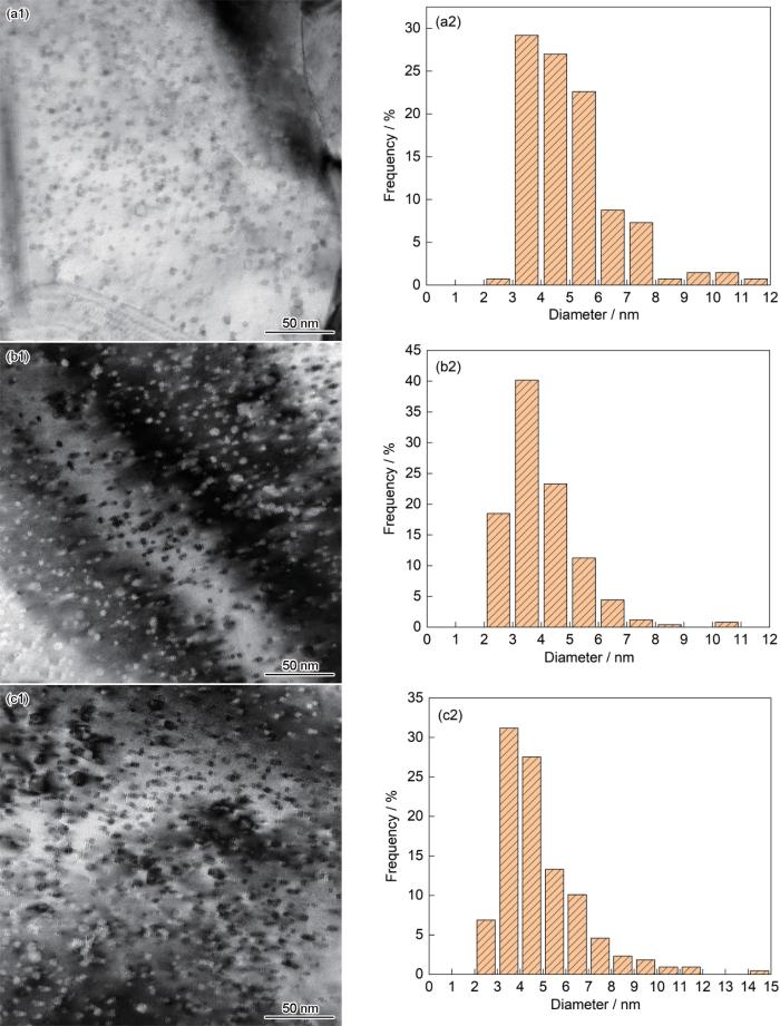
图3
不同Ti含量ODS合金的TEM明场像和纳米氧化物尺寸分布
Fig.3
TEM bright field images and size distribution of oxide particle (a) 0.2Ti, (b) 0.8Ti, (c) 1.5Ti
在用机械合金化法制备ODS合金的过程中,添加的Y2O3粉末分解为Y和O原子溶解到合金基体中。同时,高能球磨使合金粉末产生高密度空位和缺陷。这些空位和缺陷优先与O、Ti和Y等活性元素结合,促进Y-Ti-O纳米团簇形核。后续的热等静压工艺的高温高压促进O、Ti和Y元素均匀扩散,增加了Y-Ti-O纳米颗粒的形核数量和提高了结晶程度,使Y-Ti-O相复合氧化物在合金基体中弥散析出[9]。同时,Y-Ti-O相复合氧化物较强的热稳定性限制了自身晶粒的生长,因此生成的Y-Ti-O相颗粒的粒径较小[10,11]。图3给出的结果表明,在奥氏体合金中添加充足的Ti促进了Ti与Y、O的充分结合,使析出相的数密度提高和颗粒减小。
2.3 纳米氧化物的组成与Ti含量的关系
图4
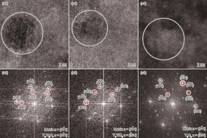
图4
0.2Ti合金内氧化物颗粒的HRTEM照片和相应的FFT衍射斑点
Fig.4
HRTEM image of oxide particles and corresponding FFT pattern in 0.2Ti alloy (a) Y2Ti2O7, (b) Y2TiO5, (c) Y2O3
图5

图5
0.8Ti合金内氧化物颗粒的HRTEM照片和相应的FFT衍射斑点
Fig.5
HRTEM image of oxide particles and corresponding FFT pattern in 0.8Ti alloy (a) Y2Ti2O7, (b) Y2TiO5
图6

图6
1.5Ti合金内氧化物颗粒的HRTEM照片和相应的FFT衍射斑点
Fig.6
HRTEM image of oxide particles and corresponding FFT pattern in 1.5Ti alloy (a) Y2Ti2O7, (b)Y2TiO5, (c) TiO2
其中dm和dp分别为基体和氧化物的两个互相平行晶面的间距。计算结果表明,Y2Ti2O7与合金基体之间的晶格错配度为5.1%。图4b所示为正交结构的Y2TiO5纳米颗粒,空间群为Pnma(62),晶格参数为a = 1.035 nm,b = 0.370 nm,c = 1.125 nm,α = β = γ = 90°。Y2TiO5与基体的取向关系为[
表1 图4中氧化物颗粒晶面间距(d)和角度(α)的测量值和理论值
Table 1
| Fig.4a | d1{ | d2{ | d3{2 | α12 | α23 | α13 |
|---|---|---|---|---|---|---|
| Measured | 0.2862 | 0.2552 | 0.2808 | 123.88° | 53.60° | 69.43° |
| Y2Ti2O7 | 0.2912 | 0.2522 | 0.2912 | 125.26° | 54.73° | 70.52° |
| d1{ | d2{403} / nm | d3{2 | α12 | α23 | α13 | |
| Measured | 0.3003 | 0.2156 | 0.2646 | 127.07° | 45.20° | 81.86° |
| Y2TiO5 | 0.2907 | 0.2129 | 0.2653 | 127.53° | 46.36° | 81.16° |
| d1{ | d2{ | d3{ | α12 | α23 | α13 | |
| Measured | 0.2393 | 0.4311 | 0.1858 | 81.89° | 54.16° | 24.73° |
| Y2O3 | 0.2363 | 0.4327 | 0.1817 | 80.40° | 55.93° | 24.46° |
图5和表2给出了0.8Ti合金中的Y2Ti2O7和Y2TiO5氧化物。与0.2Ti合金不同,0.8Ti合金中没有Y2O3纳米颗粒,纳米氧化物主要由Y2Ti2O7和Y2TiO5组成。根据测量结果,Y2Ti2O7粒子两倍的(
表2 图5中氧化物颗粒晶面间距(d)和角度(α)的测量值和理论值
Table 2
| Fig.5a | d1{ | d2{2 | d3{ | α12 | α23 | α13 |
|---|---|---|---|---|---|---|
| Measured | 0.2578 | 0.2803 | 0.2819 | 125.57° | 70.34° | 54.32° |
| Y2Ti2O7 | 0.2522 | 0.2912 | 0.2912 | 125.26° | 70.52° | 54.73° |
| d1{ | d2{01 | d3{ | α12 | α23 | α13 | |
| Measured | 0.2058 | 0.3001 | 0.1980 | 110.74° | 71.12° | 39.61° |
| Y2TiO5 | 0.2083 | 0.3091 | 0.2029 | 111.63° | 71.81° | 39.82° |
表3 图6中氧化物颗粒晶面间距(d)和角度(α)的测量值和理论值
Table3
| Fig.6a | d1{ | d2{400} / nm | d3{2 | α12 | α23 | α13 |
|---|---|---|---|---|---|---|
| Measured | 0.3070 | 0.2541 | 0.2964 | 126.27° | 53.65° | 69.61° |
| Y2Ti2O7 | 0.2912 | 0.2522 | 0.2912 | 125.26° | 54.73° | 70.52° |
| d1{ | d2{ | d3{ | α12 | α23 | α13 | |
| Measured | 0.2690 | 0.1721 | 0.2135 | 123.52° | 38.99° | 84.53° |
| Y2TiO5 | 0.2653 | 0.1721 | 0.2083 | 124.68° | 40.21° | 84.46° |
| d1{ | d2{00 | d3{ | α12 | α23 | α13 | |
| Measured | 0.4592 | 0.2892 | 0.2576 | 89.55° | 33.34° | 56.77° |
| TiO2 | 0.4594 | 0.2959 | 0.2487 | 90.00° | 32.78° | 57.21° |
表4 三种合金中氧化物粒子的种类和数量占比
Table 4
| Alloys | Y2TiO5 | Y2Ti2O7 | Y2O3 | TiO2 |
|---|---|---|---|---|
| 0.2Ti | 61.1% | 16.6% | 22.3% | 0 |
| 0.8Ti | 35.0% | 65.0% | 0 | 0 |
| 1.5Ti | 14.2% | 76.3% | 0 | 9.5% |
2.4 Ti含量对热等静压态合金硬度的影响
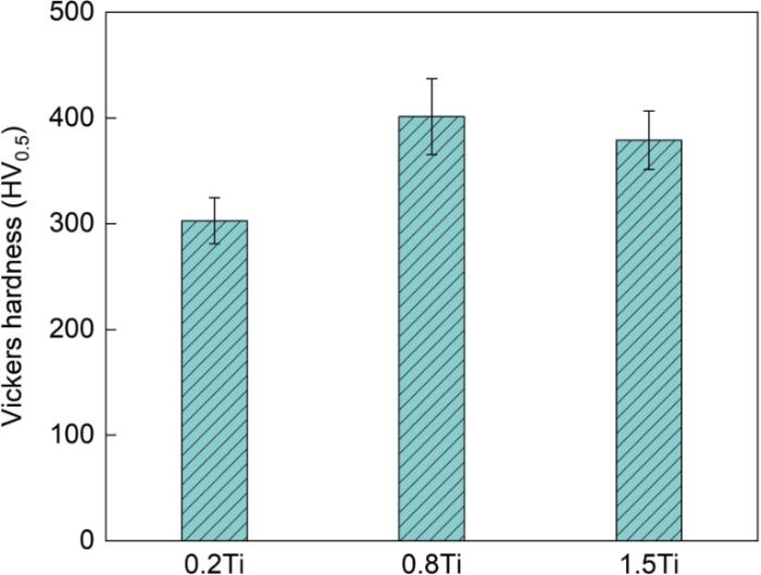
图7给出了热等静压态0.2Ti、0.8Ti和1.5Ti-ODS合金的显微硬度。3组合金的平均显微硬度分别为(302.7 ± 21.8)HV0.5,(401.3 ± 35.9)HV0.5,(379.0 ± 27.5)HV0.5。随着Ti含量的提高,合金的显微硬度呈现先提高后降低的变化趋势。将热等静压态的ODS合金与其他奥氏体合金对比,发现本文制备的合金其硬度显著高于常规15Cr-15Ni奥氏体不锈钢的硬度(250~350)HV0.1[14]。同时,这种合金的显微硬度高于Fe-13.6Cr-15.2Ni-2.0Mo-0.49Zr-0.2Y2O3和Fe-17Cr-12Ni-2.5Mo-2.0Si-1.0Y2O3 ODS合金的硬度(240~385HV1.0和257~306HV0.5)[15,16]。这表明,本文制备的ODS合金中纳米强化相的析出密度更高和分布更弥散。
图7
3 讨论
图7表明,3组合金中0.8Ti合金的显微硬度最大。结合图3、5和表4结果可见,尺寸较小的Y2TiO5和Y2Ti2O7纳米氧化物使合金的硬度提高。在合金基体中添加Ti可显著减小纳米氧化物的尺寸和提高其数密度[17,18]。在机械球磨过程中,初始Y2O3粉末分解出的Y和O原子溶解到合金基体中形成过饱和固溶体。同时,高能球磨在粉末基体中引入了高密度的位错、点缺陷、点空位和O元素,Ti和Y元素的高活性和高亲氧性使这些缺陷和空位成为纳米氧化物优选的沉淀位点,富Y和富Ti的纳米氧化物团簇在球磨粉末的氧空位处结合,在后续热固化过程中生成较细的Y-Ti-O复合氧化物[19]。基于密度泛函理论[20],Chinnappan计算了ODS合金中纳米氧化物的生成焓。结果表明,纳米氧化物的析出趋势为Y2O3 > Y2TiO5 > Y2Ti2O7 > TiO2。同时,借助DP斜率优化(Convex hull optimisation),Chinnappan又证明Y2O3与TiO2反应生成Y2TiO5(Y2O3-TiO2)和Y2Ti2O7(Y2O3-2TiO2)的概率明显高于生成其他Y-Ti-O复合氧化物的概率。因此,在本文制备的0.2Ti合金中生成Y2O3主要源于Ti元素的不足,而1.5Ti合金中生成TiO2主要源于Ti元素过量。
图8给出了Ti含量不同的奥氏体ODS合金中生成纳米氧化物的示意图。Fe-15Cr-15Ni预合金粉末与Y2O3粉末混合后进行机械合金化时,Y2O3在Ti元素的助力下快速分解,Y、O原子进入合金粉末晶格与其他合金元素在粉末内均匀扩散,借助氧空位机制[21]形成Y-Ti-O纳米团簇。在热等静压过程中,Y-Ti-O纳米团簇结晶化生成纳米强化相颗粒。在0.2Ti合金中,因Ti含量较低没有足够的Ti参与缺陷、空位处的Y-Ti-O纳米团簇形核,使基体中剩余的Y以Y-O形式形核后在高温高压下析出Y2O3颗粒,并在高温条件下长大。同理,Ti含量提高到1.5%,过量的Ti消耗了合金中的Y,剩余的Ti元素与O结合生成TiO2,在高温高压条件下TiO2颗粒长大。同时,Y2TiO5和Y2Ti2O7颗粒较高的热稳定性和硬度[22],使ODS合金的硬度显著提高。
图8

图8
不同Ti含量奥氏体ODS钢中氧化物生成的示意图
Fig.8
Schematic diagram of oxide formation in austenitic ODS steels with different Ti contents
另一方面,纳米氧化物颗粒粗化与氧化物/基体低界面能有关。根据晶界位错模型Read-Shockley方程[23]:
表5
3种合金中氧化物颗粒的δ和
Table 5
| Alloy | Types of oxide | δ / % | |
|---|---|---|---|
| 0.2Ti | Y2Ti2O7 | 5.1 | 0.42 |
| Y2TiO5 | 4.2 | 0.36 | |
| Y2O3 | 10.6 | 0.71 | |
| 0.8Ti | Y2Ti2O7 | 5.6 | 0.45 |
| Y2TiO5 | 0.2 | 0.02 | |
| 1.5Ti | Y2Ti2O7 | 5.5 | 0.44 |
| Y2TiO5 | 3.9 | 0.34 | |
| TiO2 | - | - |
根据Ostwald公式[26]:
可确定纳米氧化物颗粒半径的增长规律。其中
4 结论
(1) Ti含量的提高使Y2O3和TiO2反应的概率显著提高,适当含量(~0.8%)的Ti能促进尺寸细小的Y-Ti-O相复合氧化物颗粒在合金基体中均匀地高密度析出,在使纳米氧化物平均尺寸减小的同时还能钉扎晶界和位错使晶粒细化受到抑制和提高奥氏体15Cr-ODS合金的显微硬度。
(2) Ti含量的提高显著促进了奥氏体15Cr-ODS合金中Y-Ti-O相复合氧化物的析出,而且提高了正交结构的Y2TiO5向Y2Ti2O7的转变比例。但是,Ti含量过高会导致大尺寸TiO2颗粒生成和合金的硬度降低。
参考文献
In situ observation of damage structure in ODS austenitic steel during electron irradiation
[J].
Impact of nano-oxides and injected gas on swelling and hardening of 18Cr10NiTi stainless steel during ion irradiation
[J].
Morphology and structure evolution of Y2O3 nanoparticles in ODS steel powders during mechanical alloying and annealing
[J].
Alloying design of oxide dispersion strengthened ferritic steel for long life FBRs core materials
[J].
Effect of Ti and W on the mechanical properties and microstructure of 12%Cr base mechanical-alloyed nano-sized ODS ferritic alloys
[J].
Role of Cr and Ti contents on the microstructure and mechanical properties of ODS ferritic steels
[J].
Characterization of precipitates in nano structured 14%Cr ODS alloys for fusion application
[J].
The strength-ductility synergy of magnesium matrix nanocomposite achieved by a dual-heterostructure
[J].
Structural evolution of oxide dispersion strengthened austenitic powders during mechanical alloying and subsequent consolidation
[J].
Influence of titanium on nano-cluster (Y, Ti, O) stability in ODS ferritic materials
[J].
Study on the formation mechanism of Y-Ti-O oxides during mechanical milling and annealing treatment
[J].
Microstructures and tensile properties of an austenitic ODS heat resistance steel
[J].
Nano oxide particles in 18Cr oxide dispersion strengthened (ODS) steels with high yttria contents
[J].
Comparison of 15Cr-15Ni austenitic steel cladding tubes obtained by HPTR Cold Pilgering or by cold drawing
[J].
Effects of cold rolling and heat treatment on microstructure and mechanical properties of 15Cr-15Ni ODS austenitic steel
[J].
Effect of explosive compaction on microstructure of ODS FeCrAl alloy fabricated by oxidation method
[J].
Influence of Ti content on synthesis and characteristics of W-Ti ODS alloy
[J].
Effect of Ti and Cr on dispersion, structure and composition of oxide nano-particles in model ODS alloys
[J].
Nano-mesoscopic structure control in 9Cr-ODS ferritic steels
[J].
Thermodynamic stability of oxide phases of Fe-Cr based ODS steels via quantum mechanical calculations
[J].
Vacancy mechanism of high oxygen solubility and nucleation of stable oxygen-enriched clusters in Fe
[J].
On the coherency of Y2Ti2O7 particles with austenitic matrix of oxide dispersion strengthened steel
[J].
Oxide particle refinement in Ni-based ODS alloy
[J].
Microstructure and mechanical properties of ultrafine-grained austenitic oxide dispersion strengthened steel
[J].
Refinement of oxide particles by addition of Hf in Ni-0.5 mass%Al-1 mass%Y2O3 alloys
[J].
Effects of Hf and/or Ti addition on the morphology, crystal, and metal/oxide interface structures of nanoparticles in FeCrAl-ODS steels
[J].
