


铺层方式、搭接长度以及胶层厚度等因素均对复合材料胶接接头的性能有极大的影响,其中铺层方式因层间相互作用的改变显著影响接头的应力分布和破坏模式[8~10]。近年来大量国内外学者研究了铺层方式对单搭接接头胶接性能的影响规律[11~20]。Kadioglu F等[12]将实验与仿真相结合研究了在弯曲载荷下铺层方式([±10]5s、[±20]5s和[±45]5s)对玻璃钢(Glass-fiber reinforced plastic, GFRP)单搭接接头的破坏和力学性能的影响,发现[±20]5s和[±45]5s的单搭接接头出现分层破坏,[±10]5s发生大面积的胶层内聚破坏,且随着铺层角度的增大层间剪切效应愈加明显。毛振刚等[13]对比了[45/0/-45/90]3s、[90/45/-45/0]3s、[03/903]2s三种铺层方式CFRP(Carbon Fiber Reinforce Plastic, CFRP)单搭接接头的力学性能,发现与[45/0/-45/90]2s和[90/45/-45/0]3s相比,采用[03/903]2s铺层的胶接结构其极限失效载荷和剪切强度最大,胶接性能最好。Wang等[15]通过实验设置[0]24、[0/90]12s和[-45/904/452/-45]3s三种铺层方式,研究了铺层方式对CFRP-Al力学性能的影响,发现[-45/904/452/-45]3s能较好地抵抗剪切力。但是,目前研究铺层方式对单搭接接头胶接性能的影响大多集中于同质材料,对异质材料单搭接胶接接头的研究尚不充分,尤其是铺层方式变化对CFRP-Al胶接结构力学性能的影响及破坏机制尚不明确。鉴于此,本文使用[45/-45]4s、[0/90]4s和[0/45/-45/90]2s三种典型铺层方式的碳纤维复合材料(CFRP)与Al制备单搭接试样,在室温下进行拉伸试验,根据不同铺层方式下CFRP-Al单搭接接头的载荷-位移曲线、应变场分布及演化特征和断口形貌,研究铺层方式对接头胶接性能、失效过程及破坏特征的影响并揭示不同铺层方式下单搭接接头的破坏机制。
1 实验方法
实验用材料有碳纤维复合材料(CFRP)层合板(使用碳纤维/环氧树脂(USN15000/7901)单向预浸料用热压罐在0.26 MPa恒压下制备)、7075铝合金板和室温固化的Araldite 2015双组分环氧树脂胶粘剂。使用胶粘剂将铺层方式为[45/-45]4s、[0/90]4s和[0/45/-45/90]2s的CFRP层合板和Al制备出3组单搭接胶接试样。其制作工艺和材料参数如图3和表1和表2所示。被胶接件的尺寸均为165 mm×25 mm×2 mm,接头搭接长度为40 mm,胶层厚度为0.5 mm,结构参数在图1中给出。使用0.5 mm校准垫片和与胶接件等厚的支撑垫板控制胶层的厚度,用上、下压板对接头加压并在室温下固化。胶厚控制方法,如图2所示。为了保证实验数据的重复性和有效性,3组试样每组5个。
图1

图2
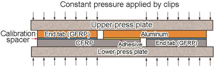
图3

表1 CFRP层合板材料性能
Table 1
| Property | Density, ρ/kg·m-3 | |||||||
|---|---|---|---|---|---|---|---|---|
| Value | 121000 | 8600 | 8600 | 3450 | 3450 | 2800 | 0.301 | 1467 |
表2 Al7075材料性能
Table 2
| Properties | Young′s modulus, E/MPa | Poisson′s ratio, | Density, ρ /kg·m-3 |
|---|---|---|---|
| Value | 71700 | 0.32 | 3000 |
使用电子万能材料试验系统对单搭接试样进行准静态拉伸试验,参照标准为ASTM D5868-01[21],设置拉伸速率为2 mm/min,下方夹持Al被胶接件,移动上方CFRP层合板实现准静态拉伸。
采用DIC设备采集与分析对胶接件搭接区域的应变场数据,在胶接件正面喷涂白色底漆和黑色散斑,面积比约为1∶1,图像采集频率为1帧/s,实验设备如图4所示。
图4

2 实验结果
2.1 试样的载荷-位移曲线
进行拉伸实验测试铺层方式为[45/-45]4s、[0/90]4s和[0/45/-45/90]2s试样的典型载荷-位移曲线,如图5所示。在三种铺层方式下[45/-45]4s试样的极限载荷最小为6.11 kN,[0/45/-45/90]2s、[0/90]4s试样的极限载荷较高,分别为11.27 kN、12.55 kN,与[45/-45]4s试样相比增大了84.5%和105.4%。[45/-45]4s试样的拉伸位移为0~1.7mm时试样进入线弹性阶段,位移为1.7~4.0 mm时进入塑性变形阶段,位移大于4.0 mm后试样断裂。与[45/-45]4s试样相比,[0/90]4s和[0/45/-45/90]2s试样的载荷-位移曲线近似为一条直线,在整个拉伸过程中均为线弹性阶段,直至最后发生脆性断裂。
图5

图5
不同铺层方式接头的载荷-位移曲线
Fig.5
Load-displacement curve of different stacking sequences
结果表明,铺层方式从[45/-45]4s到[0/45/-45/90]2s再到[0/90]4s,试样的极限载荷逐渐增大,力学性能显著提高。其主要原因是,0°铺层的纤维束与拉伸载荷在同一方向,纤维承受主要载荷,而±45°铺层主要由复合材料基体受力,其次±45°铺层在拉伸载荷作用下层间产生较大的剪切应力,使CFRP层合板内部发生剪切损伤,使极限载荷降低[14]。对比三种不同铺层方式的试样,[45/-45]4s试样的拉伸位移最大,因为CFRP板中±45°铺层的复合材料基体在拉伸载荷作用下发生了塑性变形,使纤维发生偏转和不同铺层间夹角小于90°,因此拉伸位移最大。
2.2 搭接接头应变的分布
为了探究铺层方式对接头应变分布特征的影响,使用DIC分析接头正面x方向的应变,得到接头x方向上的应变云图,比较拉伸极限载荷为10%、50%、90%时的应变场。图6给出了[45/-45]4s、[0/45/-45/90]2s和[0/90]4s铺层方式接头正面x方向的应变场。拉伸载荷为10%极限载荷时三种铺层方式接头表面的应变分布较为均匀,没有出现明显的应变集中。达到50%极限载荷时接头表面均出现应变集中区域且主要位于搭接区域的CFRP端,其中[45/-45]4s试样的应变沿45°方向分布,[0/45/-45/90]2s试样的应变沿60°方向均匀分布,而[0/90]4s试样的应变沿90°方向呈阶梯状分布。随着拉伸载荷的逐渐增大三种铺层方式接头的应变集中程度提高,达到90%极限载荷时[45/-45]4s试样的应变集中程度最高,[0/45/-45/90]2s次之,[0/90]4s最小。
图6

图6
不同铺层方式单搭接接头的正面x方向应变场
Fig.6
Strain field in front x direction of single-lap joint with different stacking sequences (a) [45/-45]4s, (b) [0/45/-45/90]2s, (c) [0/90]4s
分析三种铺层方式试样正面x方向的应变分布发现,应变都集中在CFRP端且为负值。其主要原因是,与铝合金相比CFRP的刚度较低,易在偏心弯矩作用下发生较大的弯曲变形,使接头产生负应变。同时,试样整体的应变沿铺层角度分布,且随着复合材料层合板中±45°铺层数量的增加试样的应变集中程度提高。这表明,铺层角度能在一定程度上改变接头的应变分布,与0°和90°铺层相比,±45°铺层容易使接头处产生较高的应力集中区域,应力传递能力较差,使整体的应力分布较不均匀。
2.3 破坏模式和失效形貌
为了探究铺层方式对接头破坏模式的影响,揭示不同铺层方式下接头的失效规律,分析了三种接头的破坏模式和失效形貌,如图7、8所示。结果表明,[45/-45]4s试样的破坏模式为胶层内聚破坏和复合材料层间破坏,整体是混合破坏模式(图7a),其中层间破坏所占比例较大,失效面积为84.5%。[0/45/-45/90]2s试样发生胶层内聚破坏和复合材料的层间破坏(图7b),其中内聚破坏面积为33.5%,分层破坏面积为66.5%。[0/90]4s试样整体上呈现胶层内聚破坏(图7c),占据整个失效面积的95.0%,只有较小区域呈现CFRP与胶粘剂连接表层的层间破坏,失效面积为5.0%,且CFRP邻近胶层的层间没有失效。
图7

图7
不同铺层方式单搭接接头的典型破坏模式
Fig.7
Typical failure mode of single lap joints with different stacking sequences (a) [45/-45]4s, (b) [0/45/-45/90]2s, (c) [0/90]4s
图8

图8
拉伸实验前后[45/-45]4s铺层下纤维之间夹角的SEM照片
Fig.8
SEM images of angle between fiber layers before and after tensile tests of [45/-45]4s (a) before tensile tests, (b) after tensile tests
用扫描电镜观察了图5中星形标记位置的失效形貌。分析[45/-45]4s试样中的标记“1” 发现,与拉伸实验前(图8a)相比,±45°铺层的纤维之间的夹角小于90°(图8b),表明纤维束在拉伸过程中发生偏转,复合材料的基体承受主要载荷并产生较大的塑形变形。观察标记“2”(图9a)发现,树脂断面较为平滑,纤维束并未发生断裂,在载荷作用下接头未出现脆性断裂,此时纤维束未充分体现其抗拉性能,树脂承担主要剪切载荷,因此极限载荷较低。分析[0/45/-45/90]2s试样中的标记“3”(图9b)发现,纤维上粘附着大量树脂,少量纤维束拉断。这表明,在这种铺层方式下纤维束与树脂共同承受拉伸载荷。观察[0/90]4s试样中的标记“4”(图9c)可见,界面破坏处CFRP表层0°铺层的纤维束拉断,表明在这种铺层方式充分体现了0°铺层纤维束的抗拉特性,承担主要载荷,因此接头的极限载荷较高。同时发现,树脂断面尖锐呈不规则形状,说明接头发生脆性断裂。这与[0/90]4s铺层方式下的载荷-位移曲线相同。
图9
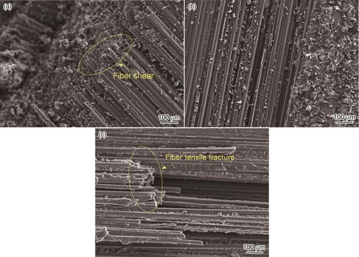
图9
不同铺层方式下单搭接接头破坏模式的SEM照片
Fig.9
SEM images of failure modes of single lap joints with different stacking sequences (a) [45/-45]4s, (b) [0/45/-45/90]2s, (c) [0/90]4s
对比三种铺层方式下接头的破坏模式和失效形貌发现,铺层方式由[45/-45]4s到[0/45/-45/90]2s再到[0/90]4s,接头的破坏整体上依次呈层间破坏、混合破坏和内聚破坏。其中层间破坏程度逐渐降低,因为随着±45°铺层数量的减少CFRP端产生应力集中的层间剪切力降低,不易产生分层破坏。同时,由于0°铺层的纤维束与载荷方向一致,与90°铺层和±45°铺层相比强度较高,因此CFRP邻近胶层0°铺层的数量越多能够承受的拉伸载荷越大,越难产生CFRP的分层破坏。三种铺层方式中[45/-45]4s试样的纤维束损伤程度最小,[0/90]4s试样的最大。其原因是,层间剪切力使试样产生损伤,随着载荷的增加损伤扩展使整层纤维束被抽出而使试样失效,纤维束不能充分发挥抗拉性能,结果是三种铺层方式的破坏模式和失效形貌不同。
3 结论
(1) 由于与载荷方向相同的纤维束可承担较大载荷且±45°铺层存在层间剪切力,因此铺层方式由[45/-45]4s到[0/45/-45/90]2s再到[0/90]4s,试样的极限载荷逐渐增大,力学性能逐渐提高。
(2) [45/-45]4s试样在拉伸过程中复合材料基体承受较大的载荷而出现塑性变形阶段,使±45°铺层间角度小于90°和试样拉伸位移最大;而[0/45/-45/90]2s和[0/90]4s试样主要由0°铺层的纤维受力,承载能力较强,主要发生脆性断裂,拉伸位移较小。
(3) 铺层角度能改变接头的应变分布特征,与0°和90°铺层相比,±45°铺层的层间剪切使接头应力传递能力较差,接头CFRP端的应力集中程度提高,使整体的应力分布较不均匀。
(4) 铺层方式由[45/-45]4s到[0/45/-45/90]2s再到[0/90]4s,接头层间剪切力逐渐减小以及CFRP层合板邻近胶层0°铺层数量的增加使其承载能力增强,破坏模式整体上依次呈现为层间破坏、混合破坏和内聚破坏。同时,分层破坏程度逐渐降低,接头纤维束的断裂数量逐渐增加,充分体现出纤维的抗拉特性。
参考文献
Overview of the application of advance composite materials on aircraft and the development of its manufacturing technology
[J].
先进复合材料在飞机上的应用及其制造技术发展概述
[J].
Characteristics of carbon-fiber-reinforced plastics (CFRP) and associated challenges—focusing on carbon-fiber-reinforced thermosetting resins (CFRTS) for aircraft
[J].
Analysis of the research status of adhesively connection technology in aerospace industry
[J].
航天工业中胶接技术的研究现状分析
[J].
An updated review of adhesively bonded joints in composite materials
[J].
Review on adhesives and surface treatments for structural applications: recent developments on sustainability and implementation for metal and composite substrates
[J].
Interaction between adherend plasticity and adhesive damage in metal/composite joints: application to bonded composite repair of metallic structures
[J].
The plasticity in the crack region is a great influence on the fatigue life of aircraft structures, and the adhesive damage has negative effects on the durability of bonded joints. In this paper, the interaction effect between the crack tip's plasticity and adhesive damage in a bonded composite repair of cracked metallic panels was analyzed using the three-dimensional finite element (FE) method. A damage criterion was implemented in the FE model to evaluate the damaged zone in the adhesive layer, and the plastic strain around the crack was extracted from the FE calculations. In this research, we have demonstrated that the applied load has very significant effects both on crack plasticity and adhesive damage, but the ductility of the repaired material has no significant effect on adhesive failure. Fatigue tests and SEM observations were performed to validate the numerical results.
Optimization of machining parameters for kerf angle and roundness error in abrasive water jet drilling of CFRP composites with different fiber orientation angles
[J].
Adhesive thickness effects on the mixed-mode fracture toughness of bonded joints
[J].
Effect of adhesive bondline thickness under salt solution on the single lap joint bonding performance
[D].
盐水环境下胶层厚度对单搭接接头粘接性能的影响研究
[D].
Effects of different overlap lengths and composite adherend thicknesses on the performance of adhesively-bonded joints under tensile and bending loadings
[J].
Progressive damage simulation of scaling effects on open-hole composite laminates under compression
[J].
Failure behaviour of the single lap joints of angle-plied composites under three point bending tests
[J].In this paper, the response of adhesively-bonded single lap joints (SLJs) with angle-plied composite adherends subjected to flexural loading was investigated. The experiments were carried out for the adherends, glass reinforced polymer matrix, with three kinds of stacking sequence. A three-dimensional finite element (FE) model was developed using ABAQUS/Explicit. The three dimensional Hashin failure criterion with an appropriate damage evolution law was used to characterize the damage inside a ply. Cohesive zone elements were used to model the damage in the adhesive layer (AF163-2K) and the interply failure, that is, the delamination. The developed numerical model was verified with the performed experiments. The SLJs of [?20](5s) and [?45](5s) failed due to failure in the adhesive layer and the delamination between the plies, whereas that of [?10](5s) failed mainly due to the former failure. The intralaminar damage was not noticed for any case. The influence of the fiber angle of plies in the adherends, adherend thickness, overlap length, and the thickness of adhesive layer on the damage in the adhesive layer and the delamination were investigated in terms of the competition between these two failures and activation of different failure modes in each thoroughly.
Effect of lap length and stacking sequence on strength and damage behaviors of adhesively bonded CFRP composite laminates
[J].
搭接长度和铺层方式对CFRP复合材料层合板胶接结构连接性能和损伤行为的影响
[J].
Failure behaviour of the adhesive layer and angle ply composite adherends in single lap joints: a numerical study
[J].
Finite element study into the effects of fiber orientations and stacking sequence on drilling induced delamination in CFRP/Al stack
[J].
Experimental study on effect of stacking sequence, clearance and clamping torque on strength of FRP composite bolted joints
[J].
Adhesive layer analysis for scarf bonded joint in CFRE composites modified with MWCNTs under tensile and fatigue loads
[J].
Experimental investigation of the mechanical and water absorption properties on fiber stacking sequences and orientation of jute/carbon epoxy hybrid composites
[J].
Abrasive wear performance of jute-glass-carbon-reinforced composites: effect of stacking sequence and fibers relative amounts
[J].
The influence of fiber orientation and stacking sequence on the crush behavior of hybrid AL/GFRP tubes under axial impact
[J].
