


传统的TiO2纳米碗阵列制备工艺[7,8,9]包括合成胶体晶模板。用物理气相、电沉积等手段负载TiO2溶胶和高温处理等流程,使用的材料多、制备过程冗杂、操作过于精细。因此,亟待开发简便、快捷和精准的合成手段。Wang等[10]用二次阳极氧化工艺制备出表面平整的TiO2纳米管阵列。二次阳极氧化工艺的原理是,剥除第一次阳极氧化的纳米管阵列,将钛片表面残余的碗状腐蚀痕迹作为第二次阳极氧化的初始氧化层,再在同等条件下进行阳极氧化。若保持第二次阳极氧化的电压、温度和电解液浓度等条件不变,减少二次阳极氧化时间使碗状坑迹纵向生长至与碗直径相当,则能制备出TiO2纳米碗阵列。Umh等[11]应用这个原理,改变二次阳极氧化电压以控制碗的直径,将不同直径的碗阵列拼凑出丰富的色彩分布。虽然两步阳极氧化法操作简便、成本低廉,但是没有深入研究氧化过程中碗内纳米孔的横向与纵向腐蚀、生长过程对TiO2纳米碗成型的影响。本文采用文献[12,13]中的最佳实验条件,只改变第二次阳极氧化时间,探究TiO2纳米孔横向与纵向的扩展与生长的变化过程并找出两者的平衡点,制备大孔径TiO2纳米碗阵列。
1 实验方法
实验用材料:纯度为99.5%的钛片、无水乙醇(分析纯AR)、丙酮(分析纯AR)、氟化铵(分析纯AR)、乙二醇(分析纯AR)、去离子水。
实验用仪器:KQ-100DE型超声波清洗器、SH-2型磁力搅拌器、SK-G06123K真空/气氛管式电阻炉、M8812型可编程直流电源。
用S4800型场扫描电子显微镜观测切片的表面形貌。
将高纯钛片裁剪成尺寸为1 cm×4 cm的切片,打磨抛光后用丙酮、无水乙醇和去离子水分别超声清洗。
将0.697 g的NH4F溶于5 mL去离子水中配制成在250 mL中有0.25%(mass fraction)NH4F和2%(volume fraction)去离子水的乙二醇电解液。阳极钛片和阴极Pt网组成两电极体系,阳极与阴极的间距为2 cm。反应温度恒定为20℃,阳极氧化电压恒定为60 V,第一次阳极氧化时间为1 h。反应结束用乙醇和去离子水充分清洗切片,随后将其放入去离子水中超声剥除表面的纳米管阵列,干燥后待用。设定第二次阳极氧化的时间分别为10、20、40、60、80、90、100、110和130 s,其他条件不变,进行第二次阳极氧化。将制备出的切片放入管式炉中,以2℃/min的升温速率将样品加热到450℃,恒温4 h后自然冷却至室温。
2 结果和讨论
在第二次阳极氧化的初始阶段(0~30 s,图1a),氧化电流大幅度下降,意味着钛片上的碗状坑迹表面开始氧化形成致密的TiO2阻挡层,电解液则开始将生长的碗口部分溶解(图1b);在随后的30~100 s,因TiO2阻挡层中心厚度最薄而承受更高的电场强度,腐蚀从中心位置开始(F-受电场力作用迁移至中心处附近,与TiO2反应生成可溶性[TiF6]-),腐蚀加快使氧化电流呈现上升的趋势。随着氧化时间的延长腐蚀由中心向四周扩展,即横向扩展。横向扩展速率的提高,促使纳米碗状结构形成。也就是,改变第二次阳极氧化的时间后,碗状结构的生成可能经历TiO2阻挡层生成阶段、纳米孔初始形成阶段和孔-碗状变化的生长阶段。
图1
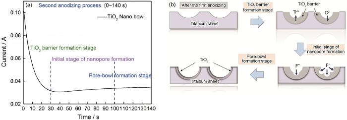
图1
TiO2纳米碗阵列在第二次阳极氧化制备过程中的时间-电流曲线和第二次阳极氧化过程的示意图
Fig.1
Current-time curves of TiO2 nano bowl array in the second anodizing process (a) and schematic diagram of the second anodizing process (b)
2.1 TiO2阻挡层的生成阶段
阻挡层的生成始于阳极氧化初期,即电解液中的O2-受电场力的作用运动到金属-氧化层界面,而Ti4+则反向迁移至氧化层-电解液界面[14],称为阻挡层的纵向生长。与此同时,电解液的化学溶解最先作用于TiO2碗口表面。实验中对应此阶段的阳极氧化时间,设定为10 s和20 s。
图2

图2
第二次阳极氧化时间为10 s和20 s时TiO2切片表面的SEM照片
Fig.2
SEM images of TiO2 surface when the second anodizing time is 10 s (a) and 20 s (b)
在短暂的阳极氧化初期TiO2阻挡层的纵向生长是主导合成因素,虽然电解液的纵向溶解也有作用,但是氧化电流的下降趋势不减,纵向生长速率高于纵向溶解速率。
2.2 纳米孔的初始形成阶段
TiO2阻挡层的生成阶段向纳米孔的初始形成阶段过渡的标志,是F-对TiO2的腐蚀。腐蚀先出现在TiO2致密层的底部,继而向四周扩展。在此阶段TiO2阻挡层的生长速率逐渐降低,纵向腐蚀较快地进行。实验中。对应此阶段的阳极氧化时间设定为40、60、80和90 s。
当第二次阳极氧化时间为40 s时碗内表面小孔的直径增大到45 nm(图3a和3b),碗口直径(91 nm)依然大于小孔直径,孔的深度约为100 nm。与氧化时间为20 s相比碗口的直径略有增大,而孔径则明显增大。这表明,F-腐蚀处于阻挡层中心位置,即从小孔周围开始腐蚀范围扩大,而横向扩展还未发生。同时,电解液的溶解速率降低,只是碗口直径稍微扩张。随着阳极氧化时间延长到60 s(图3c和3d)TiO2纳米碗口直径约为100 nm,碗内孔径约为58 nm,孔深度约为106 nm。碗口直径和碗内孔径继续增大,孔深度微微扩深,表明纵向腐蚀是合成的主导因素;由于孔深度的扩深程度小于碗口径、孔径的扩展程度,横向扩展开始发挥作用,其速率远低于纵向腐蚀的速率。
图3
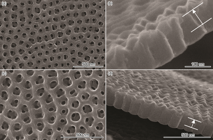
图3
第二次阳极氧化时间为40 s和60 s时TiO2切片表面的SEM照片
Fig.3
SEM images of TiO2 surface when the second anodizing time is 40 s (a, b) and 60 s (c, d)
如图4a和b所示,当第二次阳极氧化时间80 s时TiO2碗口直径约为100 nm,碗内小孔直径为55 nm,孔深度为125 nm。与氧化时间60s时TiO2碗口直径和孔径相比没有变化,但的孔的深度明显增大。由于碗径和孔径不再改变,TiO2阻挡层的纵向生长和电解液纵向溶解速率降低且达到平衡;而受阳极氧化电压的较大影响,纵向腐蚀反应剧烈迅速;由于横向扩展速率远低于纵向腐蚀速率,只是孔的深度发生变化。延长阳极氧化时间到90 s(图4c和4d),TiO2碗状阵列初步形成,碗口直径约为116 nm,孔深度约为138 nm。此时横向扩展开始“大放异彩”,横向扩展速度提高且接近纵向腐蚀速度,使碗内原来的纳米孔径扩张到与碗口直径相同;虽然有横向扩展的牵制,纵向腐蚀仍然迅速进行,使碗底再次出现小孔,孔深度的增大。
图4

图4
第二次阳极氧化时间为80 s和 90 s时TiO2切片表面的SEM照片
Fig.4
SEM images of TiO2 surface when the second anodizing time is 80 s (a, b) and 90 s (c, d)
进入纳米孔的初始形成阶段,TiO2阻挡层的生长与电解液溶解成为次要因素,纵向腐蚀和横向扩展成为主导因素。同时,纵向腐蚀较快,先从阻挡层的中心小孔处向下侵蚀,继而在碗边缘腐蚀出其他小孔并很快横向扩展、纵向腐蚀速率与横向扩展速率较快达到一个平衡界线后,纵向腐蚀速率再次提高而向金属-氧化层界面方向腐蚀。
2.3 孔-碗状变化的阶段
横向扩展与纵向腐蚀第一次平衡后,纵向腐蚀再次领先,纳米孔的深度大于碗口直径。继续延长阳极氧化时间则横向扩展速率随之提高,若再次持平或超过纵向腐蚀速率,则可得到孔径较大的TiO2纳米碗结构。这个时段,即为孔-碗状变化的生长阶段。实验中对应此阶段的阳极氧化时间设定为100、110和130 s。
图5给出了第二次阳极氧化时间100、110和130 s时TiO2的形貌,与此相应的碗口直径分别为109、133和107 nm,孔深度约为138、140和159 nm。当阳极氧化时间为100 s和130 s时碗内有纳米孔,孔径分别为70 nm和68 nm。对比阳极氧化时间为90 s时的TiO2碗口直径,阳极氧化时间延长10 s使碗口直径有所减小,且出现纳米孔,孔的深度保持不变。这表明,氧化时间为90 s时出现的小微孔在底部中心被腐蚀出后,未再深入推进,而是向四周腐蚀扩展,横向扩展速率超过纵向腐蚀速率,因此孔径增大;TiO2阻挡层继续生长,电解液对碗口的溶解效率降低,使碗径有所减小。阳极氧化时间延长到110 s,则横向扩展速率与纵向腐蚀速率保持稳定的平衡关系,碗内纳米孔消失,出现TiO2碗状阵列。碗结构完整且没有小孔,碗口直径与孔深度接近。阳极氧化时间再次延长20 s,则碗口直径和纳米孔径再次减小,孔的深度明显增大。这表明,相对平衡点再次被打破,纵向腐蚀速率超过横向扩展速率,电解液纵向溶解速率低于阻挡层纵向生长速率,碗口的直径减小。
图5
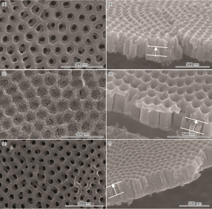
图5
第二次阳极氧化时间为100、110和130 s时TiO2切片表面的SEM照片
Fig.5
SEM images of TiO2 surface when the second anodizing time is 100 s (a, b), 110 s (c, d) and 130 s (e, f)
在孔-碗状变化的生长阶段,TiO2阻挡层的生长与电解液溶解的平衡关系不再保持,纵向溶解速率降低;与纵向腐蚀速率相比,横向扩展速率先提高后降低。当横向扩展速率与纵向腐蚀速率达到平衡临界处时TiO2纳米碗径与碗深接近,可合成出最佳的大孔径TiO2纳米碗状阵列。
3 结论
应用两步阳极氧化法原理可合成大孔径TiO2纳米碗阵列。在保持阳极氧化电压、实验温度和电解液浓度不变的条件下,随阳极氧化时间的延长TiO2阻挡层纵向生长和电解液纵向溶解、纵向腐蚀和横向扩展两两关系不断变化。在孔-碗状变化的生长阶段,四者关系维持相对稳定且平衡时,可制备出133 nm的大孔径TiO2纳米碗阵列,最佳阳极氧化时间为110 s。
参考文献
Synthesis of silver nanoparticles using the polyol process and the influence of precursor injection
[J].
Spherical silver nanoparticles with various sizes and standard deviations were synthesized by the polyol process. Two different synthesis methods were compared in order to investigate the influence of reaction parameters on the resulting particle size and its distribution. In the precursor heating method, wherein a solution containing silver nitrate was heated to the reaction temperature, the ramping rate was determined to be a critical parameter affecting the particle size. In contrast, in the precursor injection method, in which a silver nitrate aqueous solution was injected into hot ethylene glycol, because of rapid nucleation, the injection rate and the reaction temperature were important factors in terms of reducing the particle size and attaining monodispersity. Silver nanoparticles with a size of 17 +/- 2 nm were obtained at an injection rate of 2.5 ml s(-1) and a reaction temperature of 100 degrees C.
Femtosecond laser deposition of TiO2 nanoparticle-assembled films with embedded CdS nanoparticles
[J].
Dye-sensitized anodic TiO2 nanotubes
[J].
High efficiency solid-state sensitized solar cell-based on submicrometer rutile TiO2 nanorod and CH3NH3PbI3 perovskite sensitizer
[J].
Near-electric-field tuned plasmonic Au@ SiO2 and Ag@ SiO2 nanoparticles for efficient utilization in luminescence enhancement and surface-enhanced spectroscopy
[J].
Research in the Preparation and Application of Nanobowl Arrays
[J].
纳米碗阵列的制备与应用研究
[J].
Enhanced full-spectrum water splitting by confining plasmonic Au nanoparticles in N-doped TiO2 bowl nanoarrays
[J].
An organic-inorganic hybrid UV photodetector based on a TiO2 nanobowl array with high spectrum selectivity
[J].
One step route to the fabrication of arrays of TiO2 nanobowls via a complementary block copolymer templating and sol-gel process
[J].
A novel protocol toward perfect alignment of anodized TiO2 nanotubes
[J].
Tuning the structural color of a 2D photonic crystal using a bowl-like nanostructure
[J].Structural colors of the ordered photonic nanostructures are widely used as an effective platform for manipulating the propagation of light. Although several approaches have been explored in attempts to mimic the structural colors, improving the reproducibility, mechanical stability, and the economic feasibility of sophisticated photonic crystals prepared by complicated processes continues to pose a challenge. In this study, we report on an alternative, simple method for fabricating a tunable photonic crystal at room temperature. A bowl-like nanostructure of TiO2 was periodically arranged on a thin Ti sheet through a two-step anodization process where its diameters were systemically controlled by changing the applied voltage. Consequently, they displayed a broad color distribution, ranging from red to indigo, and the principal reason for color generation followed the Bragg diffraction theory. This noncolorant method was capable of reproducing a Mondrian painting on a centimeter scale without the need to employ complex architectures, where the generated structural colors were highly stable under mechanical or chemical influence. Such a color printing technique represents a potentially promising platform for practical applications for anticounterfeit trademarks, wearable sensors, and displays.
Experimental factors on preparation of ordered TiO2 Nanotubes by anodic oxidation
[J].
阳极氧化法制备有序TiO2纳米管的实验因素
[J].
TiO2 nanoring/nanotube hierarchical structure growth mechanism and optical absorption property
[J].
TiO2 纳米环/纳米管分层结构的生长机理及其吸光特性
[J].2纳米管阵列在阳极氧化过程中容易形成纳米草结构, 而利用两步阳极氧化法可制备出表面整洁的TiO2纳米环/纳米管分层结构。实验通过控制氧化时间得到了不同生长阶段的TiO2纳米环/纳米管分层结构, 并对其生长机理及吸光特性展开研究。结果表明, 在第二步阳极氧化过程中, 钛箔表面的周期性六边形纳米洞结构可以使纳米管的生长过程局限于每个纳米洞内部, 从而形成TiO2纳米环/纳米管分层结构。同时, 存在的纳米环可以为其内部的纳米管提供支撑作用, 防止纳米草结构的形成。TiO2纳米环/纳米管分层结构的吸收光谱在可见光区域呈现震荡形态, 这是纳米环顶部反射的光与钛基底反射的光相互干涉导致的。根据震荡峰形状与样品厚度的关系, 可以估算出入射光在TiO2纳米环/纳米管分层结构中的最大穿透深度为2 μm左右。]]>
